Do you have a question about the Samsung RB2155BB and is the answer not in the manual?
Identifies the specific type of refrigerator covered by this service guide.
Explains the coding system used for refrigerator models.
Details electrical components and their standards for the models.
Illustrates and describes the various shelves and bins within the refrigerator.
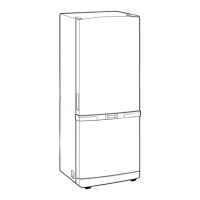
Provides detailed external dimensions of the refrigerator in inches.
Outlines the path of the refrigerant through the cooling system.
Explains how cold air is distributed throughout the refrigerator compartments.
Steps for removing and accessing the refrigerator's control panel.
Instructions for disassembling and replacing the refrigerator lamp.
Instructions for disassembling and replacing the freezer lamp.
Details on how to remove the evaporator cover in the refrigerator section.
Details on how to remove the evaporator cover in the freezer section.
Procedures for removing the evaporator unit from the refrigerator compartment.
Procedures for removing the evaporator unit from the freezer compartment.
Steps for accessing the machine compartment and electrical box.
Describes the features and layout of the digital control panel.
Explains how to adjust and set temperatures for freezer and refrigerator.
Details the operation of rapid cooling and freezing functions.
Explains the sound alerts for button presses and door alarms.
Describes how the automatic defrost cycle operates and its timing.
Instructions for manually initiating pull-down or defrost cycles.
Explains how the system recovers and resets after a power outage.
Describes a mode for showroom display, disabling compressor operation.
Details how the appliance performs self-diagnosis for potential issues.
Explains how to test individual components' output signals from the control board.
Describes condenser fan operation based on ambient temperature conditions.
Details the circuit responsible for supplying power to the control board.
Explains the circuit for clock generation and timing calculations within the MICOM.
Describes the circuit that initializes the MICOM and its memory sectors.
Details the circuit that detects the open/closed state of the refrigerator doors.
Explains how thermistors are used to sense and report temperatures to the MICOM.
Details the circuit responsible for scanning user inputs and controlling the display.
Describes the circuit that controls the operation of loads like compressors and heaters via relays.
Explains how DIP switches adjust temperature and function settings.
Provides a flowchart for troubleshooting when the appliance has no power.
Guides troubleshooting based on appliance self-diagnosis error codes.
Flowchart for diagnosing issues with the compressor not operating.
Troubleshooting steps for when the freezer fan (F-fan) fails to operate.
Troubleshooting steps for when the refrigerator fan (R-fan) fails to operate.
Troubleshooting steps for the compressor cooling fan motor issues.
Flowchart to diagnose and resolve issues related to the defrost system.
Troubleshooting steps for when the appliance's alarm sounds continuously.
Lists and illustrates the part numbers for the freezer compartment.
Lists and illustrates the part numbers for the refrigerator compartment.
Illustrates parts associated with the refrigerator door assembly.
Illustrates and lists parts belonging to the main cabinet structure.
Shows the wiring connections for the cabinet door connectors.
Provides resistance measurements for checking various loads like motors and heaters.
Details how to check the resistance of temperature and defrost sensors.
Explains how to test door switches and their signal outputs.
Describes how to use forced operation and defrosting modes for testing.
A table correlating sensor resistance and voltage with temperature values.
| Brand | Samsung |
|---|---|
| Model | RB2155BB |
| Category | Refrigerator |
| Language | English |