31
Circuit Descriptions
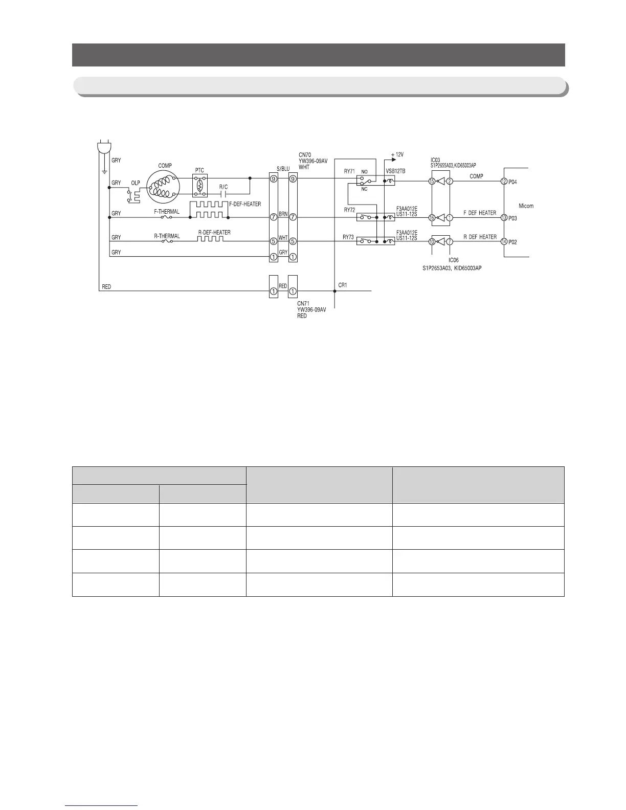
1) Most of relays can control the compressor, heaters and several option functions.
2) For the compressor, #12 pin of MICOM signals HIGH(5V). This signal enters to #2 of IC03 and #15
of output terminal will be on and grounded. When the rely RY71 is switched to NO terminal a 115V
power is supplied to the compressor. If MICOM outputs LOW(0V), the compressor will stop.
3) If the RY71 is connected to NC, RY72 and 73 for defrost heaters will be on and corresponding heater.
Will be activated according to the signal from MICOM. Like the above block diagram, operation of F,
R defrost heater is determined by the operation of the relay for COMP.
RELAY
Load
Comp Operation
Comp off, Defrost-Heater Off
Defrost-Heater On
Comp Off, Defrost-Heater Off
Remark
Defrost-Heater Power Off
Comp Power Off
COMP
on
on
off
off
Defrost Heater
off
on
on
off
10-7) Load Drive Circuit