Do you have a question about the Samsung RB31FEJNB Series and is the answer not in the manual?
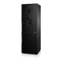
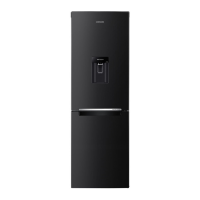
| Model | RB31FEJNB Series |
|---|---|
| Category | Refrigerator |
| Freezer Net Capacity | 98 L |
| Energy Rating | A+ |
| Energy Efficiency Class | A+ |
| Weight | 65 kg |
| Cooling Technology | No Frost |
| Color | Black |
| Noise Level | 39 dB |
| Climate Class | SN-T |
| Door Finish | Metal |
| Type | Top Freezer |
| Dimensions (H x W x D) | 1780 x 595 x 668 mm |
Overview of the refrigerator's key features and characteristics.
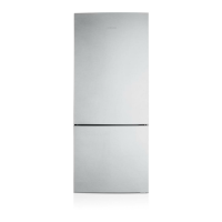
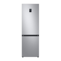
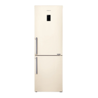
Detailed specifications for various refrigerator models.
Technical details of electrical components for different models.
Physical dimensions for various refrigerator models.
Safety precautions and required tools for disassembly procedures.
Step-by-step guide for disassembling the refrigerator door.
Procedures for disassembling minor door components.
Steps for removing refrigerator interior compartments.
Steps for removing freezer interior compartments.
Guide for disassembling components within the machine compartment.
Detailed procedure for compressor removal and installation.
Instructions for changing the refrigerator door swing direction.
Preliminary checks and diagnostic functions before detailed troubleshooting.
Details on using test modes for forced operation and defrost cycles.
Explains self-diagnosis modes, error codes, and their interpretation.
Describes how to check the load status using display LEDs.
Procedure for activating demo mode for retail display.
How to access and modify unit operational settings.
Reference table for available unit option settings.
Symptom-based troubleshooting flowcharts for common issues.
Step-by-step guide to resolve errors identified by self-diagnosis.
Troubleshooting steps for a non-operational freezer fan motor.
Diagnostic steps for issues with the defrost heater.
Troubleshooting guide for units with no power on the main PBA.
Steps to diagnose compressor issues related to the inverter PBA.
Guide to troubleshoot and resolve persistent buzzer alarms.
Identifies components and their locations on the main PCB.
Identifies components and their locations on the inverter board.
Details connectors and their functions on the main board.
Details connectors and their functions on the inverter board.
Provides electrical wiring diagrams for A+ and A++ refrigerator models.
Provides electrical wiring diagrams for A+++ refrigerator models.
Specific wiring diagrams for 3050-2M A+++ models.
Specific wiring diagrams for 3050-2M A++ models.
Illustrates the functional blocks of the main PBA.
Illustrates the functional blocks of the inverter PBA.