Do you have a question about the Samsung RF25HMEDBWW and is the answer not in the manual?
Explains warning and caution symbols and their meanings.
Essential safety warnings and list of required tools before disassembly.
Explains test modes like manual operation, forced defrost, and self-diagnostic functions.
Provides flowcharts and tables for diagnosing specific sensor and component errors.
Guides for diagnosing issues with F-FAN, R-FAN, C-FAN, and Ice Room Fans.
Shows the layout and component positions of the main PCB.
Shows the layout and component positions of the inverter PCB.
| Brand | Samsung |
|---|---|
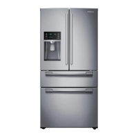
| Model | RF25HMEDBWW |
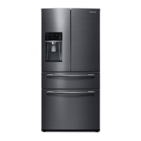
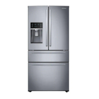
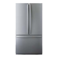
| Type | French Door |
| Total Capacity | 25 cu. ft. |
| Width | 35.75 inches |
| Height | 69.875 inches |
| Ice Maker | Yes |
| Water Dispenser | Yes |
| Energy Star Rated | Yes |
| Color | White |