Do you have a question about the Samsung RF267ABRS and is the answer not in the manual?
Essential safety guidelines for servicing the refrigerator to prevent hazards.
Explanation of symbols used to indicate potential dangers and precautions.
Specific actions that users must avoid to ensure safe operation and prevent damage.
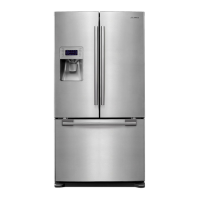
Overview of key features and technologies of the refrigerator model.
Technical details including electrical, no-load performance, and refrigeration system.
Labeled diagram of the refrigerator and freezer interior components.
Comparison of model specifications and detailed charts for various features.
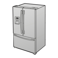
Physical dimensions in inches and specifications for optional materials.
Diagram and explanation of the refrigerant path and air flow within the unit.
Important safety notes and necessary tools before starting disassembly procedures.
Steps for removing the refrigerator door and its handle components.
Procedures for removing interior light, display cover, and water dispenser parts.
Guides for removing various shelves, drawers, and pantry components.
Procedures for disassembling the water tank, motor damper, and water filter.
Steps for removing vertical hinged sections and evaporator components.
Instructions for removing the freezer door and its pull-out drawer.
Procedures for disassembling the ice maker, freezer light, and door switch.
Steps for disassembling the motor fan, water valve, and electric box components.
Overview of diagnostic modes, error displays, and self-diagnostic functions available.
Detailed diagnostic methods for common issues like fan, defrost, power, compressor, and alarm problems.
Troubleshooting for ice maker, water dispenser, and water supply failures.
Diagnosing defrost heater, power supply, and compressor non-operation problems.
Troubleshooting continuous alarms, PCB malfunctions, and panel display problems.
Diagnosing problems related to various sensors (ice maker, ambient, F/R sensors) and motors.
Illustrated parts breakdown and list for the freezer compartment.
Illustrated parts breakdown and list for the refrigerator compartment.
Illustrated parts breakdown and list for the main cabinet structure.
Illustrated parts breakdown for the freezer door disassembly.
Illustrated parts breakdown for the left refrigerator door disassembly.
Illustrated parts breakdown for the right refrigerator door disassembly.
Diagram showing the placement of components on the main PCB.
Diagram illustrating component placement on the SMPS (Switched-Mode Power Supply) board.
Visual guide to connectors and their locations on the main PCB.
Visual guide to connectors and their locations on the SMPS board.
Comprehensive wiring diagram illustrating electrical connections for the RF267AB model.
High-level block diagram showing the overall system architecture and signal flow.
Detailed electronic circuit diagram for the appliance (part 1).
Detailed electronic circuit diagram for the appliance (part 2).
| Type | French Door |
|---|---|
| Refrigerator Capacity | 17.5 cu. ft. |
| Energy Star Certified | Yes |
| Ice Maker | Yes |
| Water Dispenser | Yes |
| Color | Stainless Steel |