Do you have a question about the Samsung RF267AE series and is the answer not in the manual?
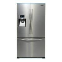
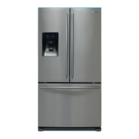
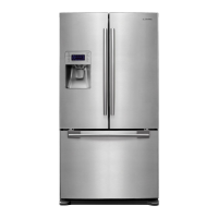
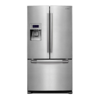
Overview of the refrigerator's key features and technologies.
Detailed technical specifications including electrical, refrigeration, and installation requirements.
Diagrams illustrating the interior layout of the refrigerator and freezer compartments.
Comprehensive chart detailing model specifications and comparisons.
Technical drawings showing the external dimensions of the refrigerator.
Details on optional parts including part names, codes, and quantities.
Diagram and description of the refrigerant flow path within the cooling system.
Visuals showing the air circulation paths within the refrigerator and freezer.
Safety guidelines and necessary tools before performing disassembly.
Step-by-step instructions for removing and disassembling the refrigerator door.
Procedure for removing and disassembling the freezer door handle.
Steps to remove and replace the refrigerator's internal light assembly.
Instructions for disassembling the display cover and water dispenser unit.
Detailed steps for removing and reassembling the water dispenser components.
Method for removing and installing the glass shelves.
Procedure for removing the foldable glass shelf.
Steps to remove the vegetable and fruit drawers and their shelves.
Instructions for disassembling the Cool Select Pantry, including cover, shelf, and rail.
Steps to disassemble and remove the water tank and its associated parts.
Procedure for removing the motor damper and its connectors.
Instructions for disassembling and removing the water filter.
Steps for correctly reassembling and installing the water filter.
Method for removing the gallon door bin.
Procedure for disassembling the vertical hinged section of the door.
Steps to remove the evaporator cover from the refrigerator compartment.
Instructions for removing the evaporator from the refrigerator compartment.
Step-by-step guide for removing the freezer door.
Method for removing the freezer's pull-out drawer.
Detailed procedure for disassembling the ice maker unit.
Steps to remove and replace the freezer's internal light.
Procedure for disassembling and checking the freezer door switch.
Steps to remove the evaporator cover from the freezer compartment.
Instructions for removing the evaporator from the freezer compartment.
Guide to disassembling components within the machine compartment, like the motor fan.
Steps for accessing and disassembling the main and inverter PCBs.
Explanation of various diagnostic modes like test mode, self-diagnosis, and option settings.
Detailed flowcharts for diagnosing specific issues based on symptoms.
Illustrated exploded views and a list of parts for the freezer section.
Illustrated exploded views and a list of parts for the refrigerator section.
Illustrated exploded views and a list of parts for the refrigerator's cabinet.
Visual guide for disassembling the freezer door components.
Visual guide for disassembling the left refrigerator door components.
Visual guide for disassembling the right refrigerator door components.
Diagram showing component placement on the main PCB.
Diagram showing component placement on the inverter board.
Layout of connectors and their part positions on the main board.
Detailed layout of the main PCB, showing component arrangement.
Layout of connectors and their part positions on the inverter board.
Wiring diagram specific to the RF267AE model.
Wiring diagram specific to the RF26XAE model.
High-level block diagram illustrating the overall system architecture.
Detailed schematic diagrams of the main and inverter circuit boards.
| Refrigerator Capacity | 17.5 cu. ft. |
|---|---|
| Ice Maker | Yes |
| Water Dispenser | Yes |
| Energy Star Certified | Yes |
| Cooling System | Twin Cooling Plus |
| Type | French Door |
| Width | 35.75 inches |
| Color | Stainless Steel |