Contents
4-2-6. If Power is not supplied ··································78
4-2-7. If compressor does not operate·······························79
4-2-8. When alarm sound continuous without stop(related with buzzer sound) ·············80
4-2-9. If Panel PCB does not work normally ····························82
4-2-10. If Pantry Panel PCB is not working normally·························83
4-2-11. When refrigerator ROOM Lamp does not light up ······················84
4-2-12. If ICE Water is not supplied ································86
4-2-13. If Water is not supplied ··································87
4-2-14. If Cubed or Crushed Ice is not supplied···························88
4-2-15. If Cover Ice Route Moor(Geard Motor) is not working normally·················89
4-2-16. If Photosynthetic LED Lamp does not work properly ·····················90
4-2-17. If Inverter PCB Power is not supplied····························91
4-2-18. If compressor does not operate ······························92
4-2-19. LED blinking frequency depending on protecting functions ··················93
Spm internal diode voltage······································94
Inverter controller board connector location ······························95
Inverter pcb circuit diagram ·····································96
4-3-1. inrush current protecting circuit ·······························97
4-3-2. power source(hybrid ic) ··································98
4-3-3. location sensing resistance area ······························99
4-3-4. sensing current area ···································100
4-3-5. comp operating signal area ································101
4-3-6. bootstrap charging area ·································102
5. PCB DIAGRAM ··········································103
5-1) PCB Layout with part position ·································104
5-2) PCB Layout with part position (SMPS Board) ···························105
5-3) Connector Layout with part position (Main Board) ·························106
5-4) Connector Layout with part position (SMPS Board) ························107
6. WIRING DIAGRAM·········································108
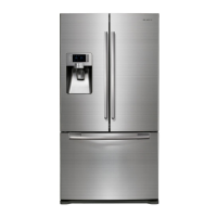
6-1) Model : RFG295AA**[BETTER] ·································108
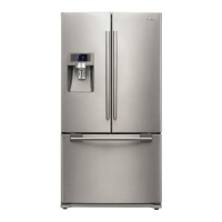
6-2) Model : RFG297AA**[BEST] ··································109
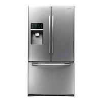
6-3) Model : RFG299AA**[7" LCD]··································110
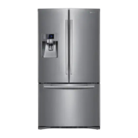
6-4) Model : RFG294AA**[SEARS] ·································111
7. SCHEMATIC DIAGRAM ·····································112
7-1) Whole block diagram ·····································112
7-1-1. MODEL : RFG295AA**[BETTER] ·····························112
7-1-2. MODEL : RFG297AA**[BEST] ······························113
7-1-3. MODEL : RFG299AA**[7" LCD] ······························114
7-1-4. MODEL : RFG294AA**[SEARS] ······························115
7-1-5. MODEL : RFG29*AA**[AW2]) ·······························116
7-2) CIRCUIT DIAGRAM ······································117
7-2-1. Main ··········································117
7-2-2. INVERTER ·······································118
 Loading...