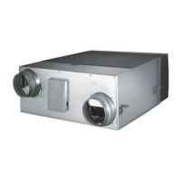
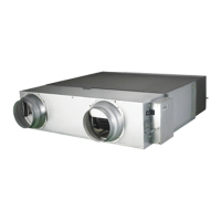
Electric Wiring (Continued)
Main PCB
② ③ ④ ⑤
⑥
⑦
⑧
⑨
⑩
⑪
①
No. Classification Explanation Specifications
1 DISPLAY DISPLAY
2
CO
2
sensor
CO
2
sensor connection port 3PIN (CN43)
3 Temperature sensor Indoor/outdoor temperature sensor connection port 4PIN (CN41)
4 Damper switch Signal input port of damper switch 3PIN (CN51)
5 External control On/Off control by external contact signal
2PIN (EXT1) / 2PIN (EXT2) /
2PIN (EXT3)
6 ERV wired remote control
V1, V2 (DC 12V power supply),
F3,F4 (ERV wired remote control communication)
4PIN (TB±COM)
7 Communication F1, F2 (Communication between the ventilators or transmitter) 2PIN (TB±COM)
8 Monitor the operation status Report operation errors 4PIN (CN77)
9 Damper motor Damper control port for changing operation modes 2PIN (CN72)
10 External device External humidifier/ External heater/ External damper 4PIN (TB±LOAD)
11 Power supply 220V/50Hz(L/N) 2PIN (TB±LOAD)
 Loading...