EasyManua.ls Logo

Samsung RJ050F2HXEA User Manual

Samsung RJ050F2HXEA
204 pages
To Next Page IconTo Next Page
Page #1 background imageLoading...
Page #1 background image
Refer to the service manual in the GSPN(see the rear cover) for the more information.
AIR CONDITIONER CONTENTS
MULTI AIR CONDITIONER
1. Precautions
2. Product Specications
3. Disassembly and Reassembly
4. Troubleshooting
5. Exploded Views and Parts List
6. PCB Diagram and Parts List
7. Wiring Diagram
8. Schematic Diagram
9. Reference Sheet
INDOOR UNIT
MH023/026/035/052FBEA
MH020/026/035/052FVEA
MH020/026/035/052FAEA
MH020/026/035/052FNEA
AQV07/09/12/18/24PSBN
AQV09/12/18YWAN
MH026/035/052FJEA
MH026/035FSEA
MH030/035/052FMEA
NJ026/035LHXEA
MH052FUEA
OUTDOOR UNIT
RJ040F2HXEA
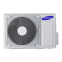
RJ050F2HXEA
RJ060F3HXEA
RJ070F4HXEA
RJ080F4HXEA
RJ100F5HXEA
Question and Answer IconNeed help?

Do you have a question about the Samsung RJ050F2HXEA and is the answer not in the manual?

Samsung RJ050F2HXEA Specifications

General IconGeneral
BrandSamsung
ModelRJ050F2HXEA
CategoryAir Conditioner
LanguageEnglish

Summary

1. Precautions

1-1 Installing the air conditioner

Guidelines for proper air conditioner installation.

1-2 Power supply and circuit breaker

Requirements for safe power connection and circuit breaker use.

2. Product Specifications

3. Disassembly and Reassembly

3-1 Outdoor Unit

Step-by-step procedure for disassembling and reassembling outdoor units.

4. Troubleshooting

4-1 Display Error and Check Method

Explains error codes displayed on indoor units and troubleshooting steps.

4-5 Fault Diagnosis by Symptom

Diagnosing issues based on specific symptoms and product behavior.

4-6 PCB Inspection

Guidelines and procedures for inspecting and replacing Printed Circuit Boards.

5. Exploded Views and Parts List

5-1 Indoor Unit

Exploded views and part numbers for various indoor unit models.

5-2 Outdoor Unit

Exploded views and part numbers for outdoor units.

6. PCB Diagram

6-1. INDOOR PCB Diagram

Diagrams showing component layout and connections for indoor unit PCBs.

6-2. OUTDOOR PCB Diagram

Diagrams illustrating outdoor unit PCB layouts and connector details.

7. Wiring Diagram

7-1. INDOOR UNIT

Wiring diagrams for various indoor unit models and their connections.

8. Schematic Diagram

9-2 Connecting Up and Purging the Circuit

9-3 Refrigerant Refill

9-6 "Pump down" Procedure

9-8 Refrigerating Cycle Diagram

Related product manuals