Samsung Electronics5-28
Alignment and Adjustment
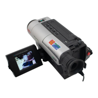
3.CCOM (VP-L300/L350 only)
1) Color bar pattern
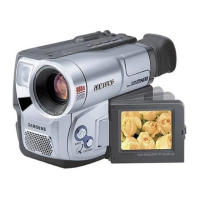
2) TP-B and LL205.
3) Connect the probe of oscilloscope to TP-B.
4) By using the "LL205" of LCD PCB, adjust the
red level carrier is minimized.
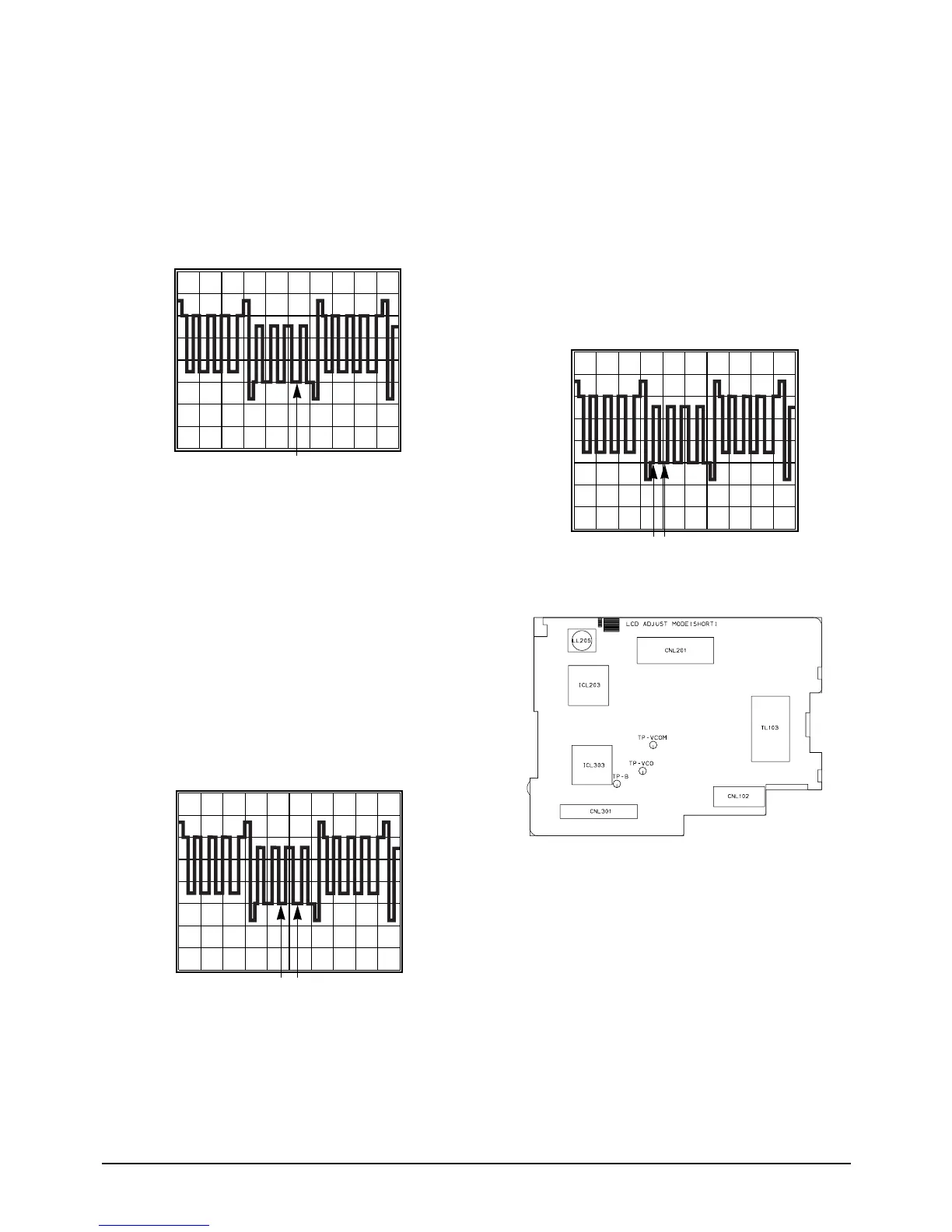
4. TINT (SCL300/L350 only)
1) Color bar pattern
2) TP B and EVR
3) Connect the probe of oscilloscope to TP-B.
4) By using "TITLE" button of unit, change the
adjustment address to 03 TINT EPR:XX
EVR:XX.
5) By using the "EDIT +/Ð" button of unit,
adjust so that the red level is same as green
level.
6) Confirm with "MENU" button of unit.
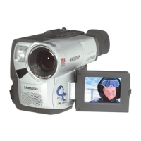
5. COLOR
1) Color bar pattern
2) TP-B and EVR
3) Connect the probe of oscilloscope to TP-B.
4) By using "TITLE" button of unit, change the
adjustment address to 04 COLOR EPR:XX
EVR:XX.
5) By using the "EDIT +/Ð" button of unit,
adjust the yellow level is same as pedestal
level.
6) Confirm with "MENU" button of unit.
6.VCOM
1) Color bar pattern
2) TP-VCOM and EVR.
3) Connect the probe of Digital Voltmeter to TP-
VCOM.
4) By using "TITLE" button of unit, change the
adjustment address to 03 TINT EPR:XX
EVR:XX.
5) Confirm with "MENU" button of unit.