Samsung Electronics4-44
Alignment and Adjustment
2-4. Adjusting Y-Emphasis Input (NORMAL)
: This adjustment is performed to set the Y level
which is recorded in tape.
Maladjusted Y level impact to the next adjust-
ment.
a. Preparations
b. Connect a power source.
c. Get into the VCR adjustment mode.
d. Press the “FADE(MODE UP)” or “BLC(MODE
DOWN)” button of FUNCTION so as to select
the address 05.
e. Insert a Normal Tape to the camcorder.
f. Connect the oscilloscope to the addressed Test
Point.
g. Press the “TITLE(DATA DOWN)/DSE(DATA
UP)” button so that the IC201 PIN13 is
0.5±0.02Vp-p from SYNC tip to peak level.
h. Be sure to press the “PROGRAM AE(CON-
FIRM)” button on FUNCTION to memorize
setting.
i. Reset the power source so as to fix the new data
to the EEPROM.
2-5. PB OUT LEVEL (NORMAL)
(Hi8 NORMAL PLAY BACK)
(NOMAL PLAY BACK OF Hi8 SET)
: This adjustment is perform to set the A/D
input level to the regulated level.
a. Preparations
b. Connect a power source.
c. Get into the VCR adjustment mode.
d. Press the “FADE(MODE UP)” or
“BLC(MODE DOWN)” button of FUNCTION
so as to select the address 06.
e. Insert the Standard Color Bar Tape and press
the “PLAY” button.
f. Connect the oscilloscope to the addressed Test
Point.
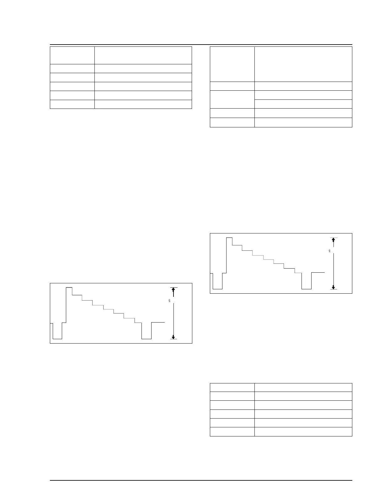
g. Press the “TITLE(DATA DOWN)/DSE(DATA
UP)” button so that the Q272 Emitter is
0.9±0.02Vp-p from SYNC to peak level.
h. Be sure to press the “PROGRAM AE(CON-
FIRM)” button on FUNCTION to memorize
setting.
i. Reset the power source so as to fix the new data
to the camcorder’s EEPROM.
2-6. Y-EMPHASIS INPUT (HI8)
a. Preparations
b. Connect a power source.
c. Get into the VCR adjustment mode.
TAPE
STANDARD COLOR BAR TAPE
RECORDED WITH SP SPEED
OSCILLOSCOPE
Q272 EMITTER
06
PB OUT-LEVEL (NOR)
EQUIPMENT
TEST POINT
ADDRESS
NAME
 Loading...