d. Press the “FADE(MODE UP)” or
“BLC(MODE DOWN)” button of FUNCTION
so as to select the address 07.
e. Insert the Hi-8 tape to the camcorder
f. Connect the oscilloscope to the addressed Test
Point.
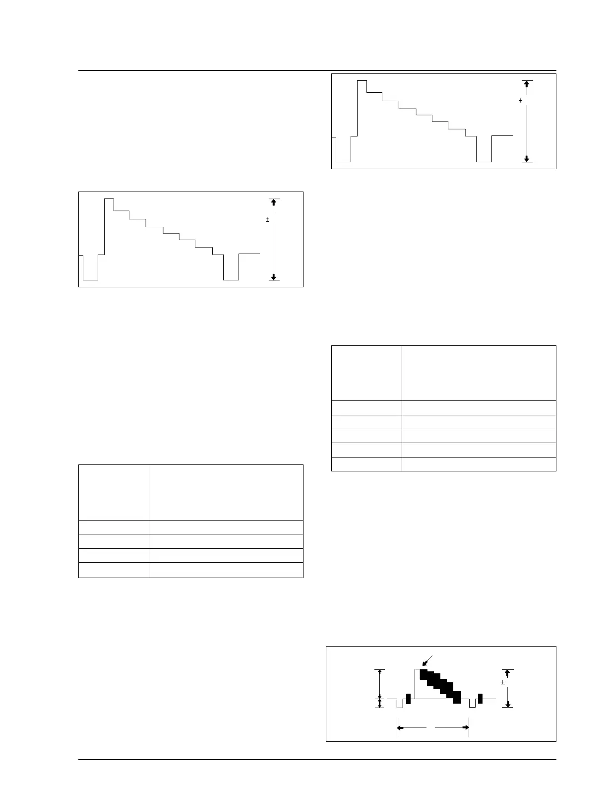
g. “TITLE(DATA DOWN)/DSE(DATA UP)” but-
ton so that the IC201 PIN13 is 0.5±0.02Vp-p
from SYNC tip to peak level.
h. Be sure to press the “PROGRAM AE(CON-
FIRM)” button on FUNCTION to memorize
setting.
i. Reset the power source so as to fix the new data
to the camcorder’s EEPROM.
2-7. PB Output Level (Hi8)
: This adjustment is performed to set the A/D
input level to the regulated level.
a. Preparations
b. Connect a power source.
c. Get into the VCR adjustment mode.
d. Press the “FADE(MODE UP)” or “BLC (MODE
DOWN)” button of FUNCTION so as to select
the address 08.
e. Insert a Hi-8 standard color bar tape and press
the PLAY button.
f. Connect the oscilloscope counter to the
addressed Test Point.
g. Press the “TITLE(DATA DOWN)/DSE(DATA
UP)” button so that the CN452 PIN13 is
0.9±0.02Vp-p from SYNC to peak level.
h. Be sure to press the “PROGRAM AE(CON-
FIRM)” button on FUNCTION to memorize
setting.
i. Reset the power source so as to fix the new data
to the camcorder’s EEPROM.
2-8. VIDEO Out Level
: This adjustment is performed to set the VIDEO
out level to the regulated level.
a. Preparations
b. Connect a power source.
c. Get into the VCR adjustment mode.
d. Press the “FADE(MODE UP)” “BLC (MODE
DOWN)” button of FUNCTION so as to select
the address 09.
e. Insert a standard color bar tape and press the
PLAY button.
f. Connect the oscilloscope counter to the
addressed Test Point.
g. Press the “TITLE(DATA DOWN)/DSE(DATA
UP)” button so that the CN452 PIN13 is
1.0±0.02Vp-p from SYNC to peak level.
Samsung Electronics 4-45
Alignment and Adjustment
 Loading...