Do you have a question about the Samsung SCX-4200/XAZ and is the answer not in the manual?
General safety guidelines for qualified service engineers and product handling.
Warnings regarding toxic materials and electric shock/fire hazards.
Information on potential hazards from leaked LCD liquid and toner powder.
Detailed safety instructions to prevent electric shock and fire hazards.
Instructions for safe operation, avoiding injury, and preventing printer damage.
Guidelines for careful part replacement, memory backup, and handling OPC drums.
Warnings about high temperatures, rotating parts, printer weight, and installation safety.
Techniques to reduce component damage from static electricity.
Cautions regarding potential explosion hazards and proper disposal.
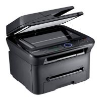
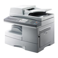
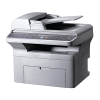
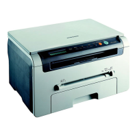
General overview of the SCX-4200/XAZ series and its market.
Detailed general technical specifications for the SCX-4200 printer.
Details on print speed, resolution, memory, and first print out time (FPOT).
Specifications for scan speed, resolution, halftone, and scan depth.
Details on copy quality, speed, resolution, zoom range, and special copy features.
Information on paper capacity, output capacity, paper sizes, and weight compatibility.
Specifications related to software, drivers, accessories, and consumables.
An overview of the printer's main components and their functions.
Describes the functions of each button and display element on the printer's control panel.
Details the hardware structure of the SCX-4200, including main control, scanner, and interface parts.
Describes the software architecture and the engine control system firmware.
Provides access to diagnostic tests for checking engine components and their conditions.
Illustrates the path paper takes through the printer and identifies jam points.
Instructions for clearing paper jams based on error messages displayed on the LCD.
Procedure for printing the system data report to confirm user-selectable option settings.
Allows selective clearing of machine memory, including paper settings, copy setup, and all settings.
Procedure for cleaning the OPC drum to resolve streaks or spots on prints.
Provides a guideline for the replacement cycle of consumables and parts.
Lists LCD error messages, their meanings, and suggested solutions.
Helps identify rollers causing periodic printing defects by measuring repetition intervals.
A comprehensive list of error messages, their meanings, and recommended solutions.
Important cautions for disassembling and reassembling printer components, including cable routing and part handling.
Step-by-step instructions for removing and installing the front cover.
Instructions for removing the rear cover and its associated components.
Procedure for removing and replacing the DC fan assembly.
Steps for removing and installing the right side cover of the printer.
Instructions for removing and installing the left side cover of the printer.
Detailed steps for removing and reinstalling the scanner unit and its related parts.
Instructions for disassembling and reassembling the Operator Panel (OPE) unit.
Procedure for removing and reinstalling the middle cover unit.
Step-by-step guide for removing and replacing the fuser unit and its internal components.
Instructions for removing and replacing the exit roller assembly.
Procedure for removing and reinstalling the Laser Scanner Unit (LSU).
Steps for removing and replacing the printer's cooling fan.
Instructions for removing and reinstalling the drive assembly, including motor and gears.
Procedure for removing and reinstalling the engine shield assembly.
Steps for removing and replacing the Main Printed Board Assembly (PBA).
Instructions for removing and replacing the Switching Mode Power Supply (SMPS).
Procedure for removing and replacing the CRUM (Chip-based Randomly-updated Memory) PCB.
Instructions for removing and replacing the transfer roller and associated components.
Steps for removing and replacing the feed roller assembly and gears.
Instructions for removing and replacing the pick-up roller and solenoid assemblies.
A flowchart-based approach to diagnosing printer issues based on symptoms.
Addresses common printing issues like vertical lines and bands, their causes, and solutions.
Troubleshooting for copy-related issues like white or black copies.
Troubleshooting for issues related to incorrect print positioning and paper feeding jams.
Addresses common printer faults like fuser errors and LSU errors reported on the LCD.
Guidelines for using Samsung toner cartridges and servicing for toner life.
A visual representation of the printer's system components and their interconnections.
An exploded view illustrating the main assembly of the printer.
Exploded view showing the components of the printer's housing base.
Exploded view detailing the various parts that make up the printer's frame assembly.
Exploded view of the fuser unit, showing its internal components.
Exploded view illustrating the components of the printer's drive assembly.
Exploded view of the scanner assembly, showing its parts and their arrangement.
Exploded view of the Operator Panel (OPE) assembly, detailing its components.
Exploded view illustrating the parts that constitute the printer's cassette assembly.
A comprehensive list of all printer parts with their codes, descriptions, and service availability.
Illustrates the electrical connections between the main controller and various printer units.
Schematic diagram for the main controller board of the SCX-4200 printer.
Circuit diagram for the Operator Panel (OPE) interface, including LCD and key inputs.
Schematic diagram for the SMPS (Switching Mode Power Supply) operating at 110V.
Schematic diagram for the SMPS (Switching Mode Power Supply) operating at 220V.
Lists recommended tools for performing printer troubleshooting and maintenance.
A glossary of acronyms and abbreviations used throughout the service manual.
Guidelines for choosing an appropriate environment and location for printer installation.
Displays a standard test pattern for print quality evaluation.
| Functions | Print, Copy, Scan |
|---|---|
| Printing Technology | Laser |
| Monochrome/Color | Monochrome |
| Print Speed | Up to 20 ppm |
| Print Resolution | 1200 x 1200 dpi |
| Monthly Duty Cycle | 20, 000 pages |
| Copy Speed | Up to 20 cpm |
| Copy Resolution | 600 x 600 dpi |
| Scanner Type | Flatbed |
| Scan Resolution | 1200 x 1200 dpi |
| Paper Capacity | 250 sheets |
| Input Tray Capacity | 250 sheets |
| Connectivity | USB 2.0 |
| Media Type | Labels, Envelopes |
| Standard Media Size | A4 |
| Operating System Compatibility | Windows, Mac, Linux |
| Type | Multifunction Laser Printer |