Do you have a question about the Samsung SL-M4080FX and is the answer not in the manual?
Safety guidelines for servicing and handling the product.
Important safety warnings regarding toxic materials, electrical hazards, and handling.
Procedures to prevent Electrostatic Discharge damage to sensitive components.
High-level summary of printer features and capabilities.
Detailed technical specifications including performance, dimensions, and power.
General specs: processor, memory, storage, interfaces, warmup, temp, humidity, noise, power.
Print speed, resolution, languages, and client OS support.
Scan speeds, resolutions, file formats, destinations, and sizes.
Copy speeds, resolutions, enlargement/reduction, and features.
Fax compatibility, modem speed, scan/resolution, compression, and features.
Paper capacity, media sizes, types, weight, and sensing for trays.
List of available software applications and management solutions.
Information on toner cartridge models and their expected life.
List of key maintenance parts with part codes and lifespan.
Available optional accessories like trays, memory, and wireless kits.
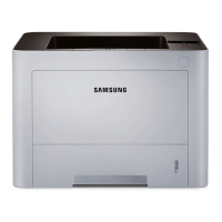
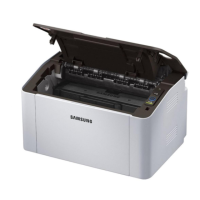
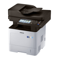
Diagrams and labels for the printer's front and rear views.
Overview of paper feeding mechanisms.
Explains components involved in paper pickup and transport.
Specification and details of the basic paper cassette (Tray 1).
Description of the unit responsible for picking up paper.
Specification for feeding specialty media and custom sizes.
Explanation of the printing process.
Describes the steps from toner to printed image.
Details about the integrated toner cartridge structure and development.
Components and function of the fuser unit.
Overview of the LSU and its components.
Basic components and function of the LSU.
Explanation of the laser beam path within the LSU.
Overview of the printer's drive motors.
Lists drive motors, their types, quantities, and functions.
Details of the main drive unit's front and rear views.
Information on the exit drive unit and its power train.
Details of the tray lifting drive unit and its power train.
Overview of the scanner system.
Explains scanner operation and CIS technology.
Description of components like input tray, pickup module, and CIS.
Overview of the printer's electrical circuit system.
Detailed information and connection points of the main board.
Information on the Operator Panel (OPE) and its LCD.
Details about the system memory module.
Information on the CRUM PBA for toner cartridge counting.
Description of the fax modem card.
Details of the SCF board for optional cassettes.
Information on the optional NFC board.
Details of the Switching Mode Power Supply board.
Information on the High Voltage Power Supply board.
Diagrams showing the location of sensors and motors.
General precautions for disassembling and handling parts.
Specific warnings for assembly, disassembly, and screw usage.
Guidelines for safely handling Printed Circuit Boards (PCBs).
Method for carefully releasing plastic latches on parts.
Procedures for replacing common maintenance parts.
Step-by-step guide to replace the fuser unit.
Procedure for removing and replacing the transfer roller.
Steps to remove the separation roller.
Procedure for replacing pick-up and forward rollers.
Steps to remove the SCF separation roller.
Procedure for replacing SCF pick-up and forward rollers.
Procedures for replacing major internal components.
Steps to remove the printer's right cover.
Steps to remove the printer's left cover.
Procedure for removing the rear cover.
Steps to remove and replace the main logic board.
Procedure for removing and replacing the Hard Disk Drive.
Steps to remove and replace the High Voltage Power Supply board.
Procedure for removing and replacing the Switching Mode Power Supply board.
Steps to remove and replace the duplex motor.
Procedure for removing and replacing the fuser drive unit.
Steps to remove and replace the main drive unit.
Procedure for removing and replacing the CST-lifting drive unit.
Steps to remove and replace the paper size sensor.
Procedure for removing and replacing the Operator Panel Electronics unit.
Steps to remove and replace the scanner unit.
Procedure for removing and replacing the Duplex Single Document Feeder unit.
Steps to remove and replace the fax board.
Procedure for removing and replacing the middle cover.
Steps to remove and replace the Laser Scanning Unit.
Procedure for removing and replacing the exit unit.
Steps to remove and replace the bin-full sensor.
Procedure for removing and replacing the Multi-Purpose unit.
Steps to remove and replace the MP roller assembly.
Disassembly of the second cassette feeder.
Procedure to remove the PBA-SCF from the second cassette feeder.
Steps to remove the lift unit from the second cassette feeder.
Procedure for removing the clutch from the second cassette feeder.
Steps to remove the drive unit from the second cassette feeder.
Overview of the control panel buttons and display functions.
Explains the display screen layout and interactive elements.
Explains the meaning of different status LED colors and patterns.
Instructions for updating the printer's firmware.
Step-by-step guide to update firmware via USB.
Guide for updating firmware over the network.
Procedures for clearing paper jams in various locations.
Detailed steps for clearing paper jams from trays and internal areas.
Instructions for clearing jams in the document feeder.
Information on tools for managing the printer.
Setup and usage of the SyncThru™ Web Service.
Overview of the Samsung Easy Printer Manager application.
Procedures for accessing and using the service mode.
Steps to enter and exit the service mode.
Hierarchical menu structure for service mode functions.
How to access machine information like serial number and status.
How to view fault, jam, and part replacement counts.
Procedures for engine, fax, and scanner diagnostics.
Explanation of various service functions like memory clear and port management.
General procedures for diagnosing and resolving printer issues.
Flowchart for initial troubleshooting steps.
Comprehensive list of error codes and their troubleshooting steps.
Troubleshooting for paper mismatch errors.
Troubleshooting for motor or fan sensor errors.
Troubleshooting for toner cartridge related errors.
Troubleshooting for errors related to optional cassettes.
Troubleshooting for paper jam errors in various trays.
Troubleshooting for general system errors.
Troubleshooting for fuser unit related errors.
Troubleshooting for LSU motor errors.
Troubleshooting for DSDF (document feeder) jams.
Guide to diagnosing and resolving print quality issues.
Troubleshooting for common errors like multi-feeding and no-power.
A high-level functional block diagram of the printer's system.
Diagram showing the electrical connections between major components.
List of recommended tools for troubleshooting.
Definitions of technical terms used in the manual.
Sample print pattern for testing toner cartridge and print speed.
Explanation of the printer's model naming structure and codes.
List of manual versions and their release dates.
| Style | Multifunction |
|---|---|
| Color | Black / White |
| Control Panel | 7” Touchscreen Panel |
| Noise Level | Copying: 56 dBA |
| Interface Connectors | 1 x USB 2.0 |
| Wireless Connectivity | Wi-Fi Direct |
| Apple Macintosh OS X 10.5 or later; Linux | Windows 10 |
| Mac OS® X 10.6.8 – 10.10.x8 | Windows Vista |
| MPT: Min. A6R - Max. A4R (Legal) | 16:9 |
| MPT: Min. A6R – Max. A4 (Legal) | 3.5 in x 5 in |
| Duplex Printing: A4 / Letter / Oficio / Folio / Legal / JIS B5 / ISO B5 / Executive / Statement | C4 (Envelope) |
| Manual Feed Slot: Letter | A5 |
| Functions | |
| Features | PC-Free Printing |
| Printing Method | Epson Micro Piezo |
| Nozzles | - |
| First Page Print Time | From Ready: As fast as 6 sec |
| Warm Up Time | |
| Print Resolution | 1200 x 1200 dpi |
| Scanner Type | - |
| 300 DPI 9 | Mono 35 ipm / 60 ipm (@ 300 dpi) |
| Scan Resolution | Optical Up to 600 x 600 dpi |
| Scan Formats | - |
| Copy Modes | photo |
| Max Copies | 999 |
| Copy Size | - |
| Copy Scale | 25 - 400% |
| Power Consumption | 3 |
| Battery Life | - |
| Battery Capacity | - |
| Depth | 481.4 mm |
|---|---|
| Height | 576 mm |
| Width | 530 mm |
| Net Weight | 30.9 lb |