
S
Sean SmithAug 15, 2025
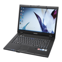
What to do if no picture appears on my Samsung SENS R60 Plus Laptop screen?
- PpennyowensAug 15, 2025
If your Samsung Laptop displays no picture, start by checking the connection between the LCD module and cable, the LCD cable and the main board LCD connector, and the LCD cable and the LCD inverter. Also, verify if the System LED on the main board is blinking, indicating operation. Further, check if the memory module is working correctly and ensure the power button can be pressed normally.