
J
Jason CraneAug 3, 2025
Why is the TIMER LED blinking on my Samsung Air Conditioner?
- RryanparkAug 4, 2025
If your Samsung Air Conditioner displays an Indoor unit Room sensor Error, it means the TIMER LED is blinking at a frequency of 1Hz.
Why is the TIMER LED blinking on my Samsung Air Conditioner?
If your Samsung Air Conditioner displays an Indoor unit Room sensor Error, it means the TIMER LED is blinking at a frequency of 1Hz.
What does it mean when the STD, Nature, and TIMER LEDs are blinking on my Samsung SH24TAB5 Air Conditioner?
If your Samsung Air Conditioner shows an EEPROM Error, it means that the STD, Nature, and TIMER LEDs are blinking at a frequency of 1Hz.
What does it mean if the STD and TIMER LEDs are blinking on my Samsung Air Conditioner?
If your Samsung Air Conditioner shows an Indoor unit heat exchanger temperature sensor Error, the STD and TIMER LEDs will blink at a frequency of 1Hz.
Always disconnect the power cord from the circuit breaker before performing any repair.
Use only exact replacement parts; consider replacing rather than repairing.
Use correct tools and test equipment to prevent future problems.
Check the power cord prior to repair and replace if necessary.
Avoid extension cords and tapping into power cords to prevent malfunction or fire.
After reassembly, measure resistance between power cord and ground terminal (>30 megohms).
Confirm that grounding connections are adequate.
Verify installation conditions are satisfactory; relocate if necessary.
Ensure children are kept away from the unit while it is being repaired.
Be sure to clean the unit and its surrounding area before and after service.
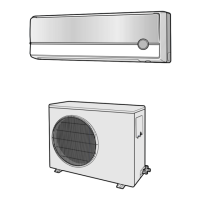
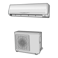
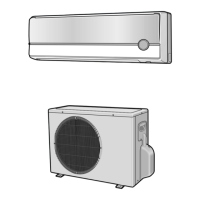
Details of key components for indoor and outdoor units across models.
Physical dimensions and package sizes for indoor and outdoor units.
Graphs showing low pressure vs. outdoor inlet air temperature.
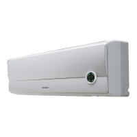
Guide to remote controller functions and operation modes.
Guidelines for selecting installation locations for units.
Step-by-step procedures for taking apart the indoor unit.
Step-by-step procedures for taking apart the outdoor unit.
Initial checks and common issues before detailed diagnosis.
Procedures to diagnose faults based on symptoms and indicators.
Instructions and safety precautions for replacing PCB modules.
Guidelines for inspecting PCBs and replacing faulty parts.
Diagrams and part numbers for indoor unit components.
Diagrams and part numbers for outdoor unit components.
Exploded views and part lists for remote control and PCB box.
Diagram illustrating the air conditioner's refrigerating cycle.
Circuit diagrams for the main printed circuit boards.
PCB diagrams for AS18A(B)9(0)RE/D, SC18A(B)9 and display module.
Wiring schematics specific to the indoor unit.
Wiring schematics specific to the outdoor unit.
Detailed circuit schematics for the indoor unit.
Additional detailed circuit schematics for the indoor unit.
| Power Supply | 220-240V, 50Hz |
|---|---|
| Refrigerant | R410A |
| Cooling Capacity | 24000 BTU/h |
| EER | 3.21 |
| Operating Temperature (Cooling) | 16-46°C |
| Noise Level (Indoor) | 42 dB(A) |