Do you have a question about the Samsung SH24TP6 A and is the answer not in the manual?
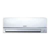
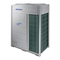
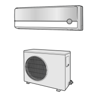
Detailed technical specifications for various models, including performance and dimensions.
Graphical representation of pressure variations based on outdoor air temperature.
Detailed explanation of each button and its function on the remote control.
System status check and error code reporting for troubleshooting.
Audible alerts indicating operational status changes or errors.
Guidelines and requirements for selecting the installation area for the unit.
Step-by-step guide for disassembling the indoor unit components.
Step-by-step guide for disassembling the outdoor unit components.
Diagrams and part numbers for the indoor unit components.
Diagrams and part numbers for the outdoor unit components.
Detailed assembly diagram and parts list for the indoor control unit.
Visual representation of the refrigerant flow and system components.
Schematic and parts list for the AC main printed circuit board.
Schematic and parts list for the DC main printed circuit board.
Schematic and parts list for the display assembly PCB.
Schematic and parts list for the module assembly PCB.
Wiring schematic for the indoor unit, showing component connections.
Wiring schematic for the outdoor unit, showing component connections.
Detailed electronic schematics for the indoor unit's main board.
Specific schematic for DC part of 24K/18K BTU models.
| Refrigerant | R410A |
|---|---|
| Type | Split Type |
| Cooling Capacity | 24000 BTU/hr |
| Power Supply | 220-240V, 50Hz |
| Operating Temperature (Cooling) | 18°C - 43°C |