Do you have a question about the Samsung SR-648EV and is the answer not in the manual?
Lists the main sections and topics covered in the service manual.
Explains warning and caution symbols and their meanings for user safety.
Defines various symbols used in the manual related to safety and operation.
Details specific precautions related to storing food and handling components safely.
Details the operation and settings for controlling the freezer compartment temperature.
Explains how to adjust and manage the temperature in the refrigerator section.
Explains the self-diagnosis routine performed when the refrigerator is first powered on.
Provides a table correlating error codes and display symptoms with specific issues.
Step-by-step guide for disassembling the cooling system components in the refrigerator.
Instructions for disassembling the cooling system components within the freezer.
Provides a troubleshooting guide for common issues with the water dispenser.
Details the temperature sensing components and their electrical characteristics.
Explains the operating logic for the compressor and defrosting heaters.
Guide for checking the main PCB for failures and performing self-diagnosis.
Provides voltage and resistance data for temperature sensors at various temperatures.
Troubleshooting steps for when the refrigerator does not receive power.
Steps to diagnose and resolve outer temperature sensor failures.
Troubleshooting steps for R1, R2, and refrigerator temperature sensor failures.
Diagnoses and resolves refrigerator defrosting sensor issues.
Troubleshooting steps for F1 and freezer temperature sensor failures.
Diagnoses and resolves freezer defrosting sensor failures.
Troubleshooting steps for when the panel PCB does not display any information.
Steps to resolve issues where panel PCB key selections are not recognized.
| Defrost System | Frost Free |
|---|---|
| Number of Doors | 2 |
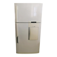
| Color | Silver |
| Capacity | 648 liters |
| Total Capacity | 648 liters |
| Energy Rating | A |