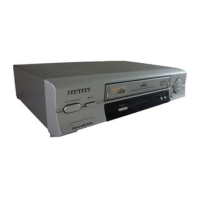
Do you have a question about the Samsung SV-220B and is the answer not in the manual?
Location for assembling the mode switch on the main PCB.
Procedure to manually eject a cassette when the unit is inoperable.
Procedures for AC leakage, antenna cold, and high voltage safety checks.
Handling ESD components, picture tube implosion, and design alteration warnings.
Warnings regarding hot chassis and product safety notices for component replacement.
Details on adjustments and required remote control for VCR servicing.
Identifies the location of the test switch for entering adjustment modes.
Procedures for ACE head height, tilt, audio azimuth, and X-point adjustments.
Procedures for tape wrinkle checks, linearity, and operational adjustments.
Checking reel torque and adjusting tension pole location.
Visual identification of cabinet components and their locations.
Exploded views identifying mechanical parts from top and bottom.
List of parts for the Switched-Mode Power Supply.
Overview of functional blocks on the main PCB.
Schematics for SMPS (230V/Free Voltage) and Power Drive circuits.
Schematics for System Control, Audio/Video, Hi-Fi, TM-Block, SECAM.
Schematics for A2/NICAM, Input-Output, OSD, and Timer functions.
Schematics for Remote Controls, F-A/V Jacks, and SRC/Shuttle.
Procedures for disassembling and reassembling the VHS deck.
Identifies mechanical parts from top and bottom views of the deck.
Steps for removing and reassembling various components from the main deck.
Procedures for manual cassette ejection and motor capstan removal.
Table detailing clearing, lubrication, and replacement times for principal parts.
Procedures for aligning and adjusting the VHS deck components.
Identifies adjustment points for the tape transport system.
Procedures for ACE head height, tilt, audio azimuth, and X-point adjustments.
Procedures for linearity, tape wrinkle, reel torque, and tension post adjustments.