6-3
6. Wiring Diagram
6-3. Connector Functions
Connector Functions
$/
Transmits LVDS signals from the Main board to the panel
* When a problem occurs: The Blank Screen and No Power errors may occur.
$/
VGA signal input terminal
* When a problem occurs: The No RGB Output error may occur.
$/
DVI signal input terminal
* When a problem occurs: The No DVI Output error may occur.
$/
HDMI signal input terminal
* When a problem occurs: The No DVI Output error may occur.
$/
HDMI signal input termianl
*When a problem occurs: The No DVI Output error may occur.
$/
Supplies 5V and 13V from the Power board to the Main board. Receives and transmits the
PWM output to the Inverter.
* When a problem occurs: The Blank Screen and No Power errors may occur.
$/
Component input terminal.
* When a problem occurs: The No MIC Input error may occur.
+"
SCART input terminal.
* When a problem occurs: The No WebCam Input error may occur.
+"
PC Audio input terminal.
* When a problem occurs: The No Speaker Output error may occur.
01
Digital Audio output terminal.
* When a problem occurs: The No USB Download Operating error may occur.
$/
Component Audio input terminal.
* When a problem occurs: The No Speaker Output error may occur.
CN2003 Headphone output terminal.
JA3005 DTV Code download terminal
6-4. Cables
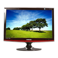
Use LVDS 30P FFC cable
Code 20” : BN96-07252B 22” : BN96-07252D
Photo
 Loading...
