Do you have a question about the Samsung TH060EAV and is the answer not in the manual?
Guidelines for safe and proper installation by authorized personnel.
Instructions for safe electrical connection and circuit protection.
Safety measures and recommendations for operating the air conditioner.
Proper procedures for discarding the air conditioner and its components.
General guidelines, including supervision for users and current measurement standards.
Highlights key performance and design aspects of the product.
Detailed technical specifications for various models, including capacity and dimensions.
Compares specifications between different product models for easy selection.
Lists available accessories and optional components with their codes.
Explains indoor unit LED error codes and troubleshooting steps.
Guides on how to set unit options using the remote control.
Step-by-step procedure for disassembling the indoor unit components.
Step-by-step procedure for disassembling the outdoor unit components.
Illustrates the internal components of the indoor unit with part numbers.
Shows an exploded view and parts list for the unit's panel assembly.
Illustrates the external components of the outdoor unit with part numbers.
Provides an exploded view and parts list for the control assembly.
Lists electrical components for the indoor PCB DB93-03451A.
Lists components for the outdoor main PCB UH026EAV/UH035EAV.
Lists components for the outdoor main PCB UH052EAV.
Lists components for the outdoor main PCB UH060EAV.
Wiring diagram for the indoor unit, showing component connections.
Wiring diagram for outdoor units (UH026EAV/UH035EAV).
Circuit schematic for the indoor unit, showing detailed electronic components.
Circuit schematic for outdoor units (UH026EAV/UH035EAV).
Detailed description of PCB circuits, including indoor and outdoor units.
Illustrates the refrigerant flow and cycle in the air conditioner system.
Shows the layout and component numbering for the indoor PCB.
Shows the layout and component numbering for the outdoor PCB.
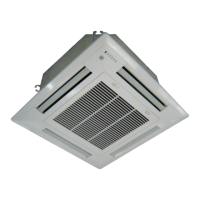
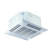
Identifies and labels key parts of the indoor and outdoor units.
Explains how to operate the main functions using the remote controllers.
Details the buttons and display of the wireless remote control.
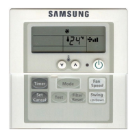
Details the buttons and display of the wired remote controller.
Initial checks for common operational issues before detailed diagnosis.
Systematic troubleshooting guide for various error symptoms.
Procedures for inspecting and testing PCBs for faults.
Guide for checking the resistance of key components like sensors and motors.
Illustrates the functional blocks and connections within the indoor unit.
Illustrates the functional blocks and connections within the outdoor unit.
Provides a guide for understanding model code structure and options.
Displays pressure graphs and tables for capacity data.
Addresses common non-trouble issues and their solutions.
Guidelines and procedures for installing the air conditioner.
| Brand | Samsung |
|---|---|
| Model | TH060EAV |
| Category | Air Conditioner |
| Language | English |