3. Installing the Product
English 8/2020. Rev 0.3 47
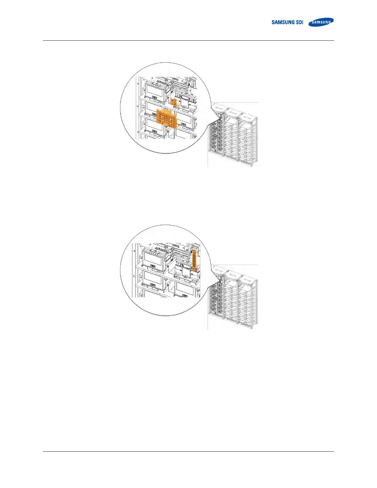
1. Remove Battery Module #1’s front cover and the SMU B- terminal cover.
Figure 3-39: Removing the Module #1’s Cover and SMU B- Terminal Cover
2. Connect SMU B- and Module #1 B- using “BUSBAR M TO SMU.” SMU B- terminal is connected using an M12 screw and
Battery Module #1 B- terminal is connected using an M8 screw. Measure the contact resistance between the terminals and
the bus bar.
Figure 3-40: Connect SMU B- and Module #1 B-
 Loading...