EasyManua.ls Logo

Samsung UH035EAV1 User Manual

Samsung UH035EAV1
90 pages
To Next Page IconTo Next Page
Page #1 background imageLoading...
Page #1 background image
Refer to the service manual in the GSPN(see the rear cover) for the more information.
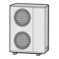
AIR CONDITIONER CONTENTS
SYSTEM AIR CONDITIONER
Model
: JH035EAV Series
JH026EAV Series
UH035EAV Series
UH026EAV Series
Model Code :
JH035EAV1
JH026EAV1
UH035EAV1
UH026EAV1
1. Precautions
2. Product Specifications
3. Disassembly and Reassembly
4. Troubleshooting
5. Exploded Views and Parts List
6. PCB Diagram and Parts List
7. Wiring Diagram
8. Schematic Diagram
9. Reference Sheet
UH026EAV1
UH035EAV1
JH026EAV1
JH035EAV1

Table of Contents

Questions and Answers:

Samsung UH035EAV1 Specifications

General IconGeneral
BrandSamsung
ModelUH035EAV1
CategoryAir Conditioner
LanguageEnglish

Summary

Safety and Precautions

1-1 Precautions for the Service

General guidelines for servicing the unit, emphasizing standard parts and harness repair.

1-2 Precautions for Static Electricity and PL

Warnings about static electricity effects on PCBs and prohibition of consumer repairs.

1-3 Precautions for Safety

Safety measures for electrical hazards, wiring, power cords, and unattended use.

Product Specifications and Features

2-1 Product Features

Highlights key features like Console Type, MPI Zone, Special Filter, Flexible Pipe Installation, and Elegance Design.

2-2 Product Specifications

Detailed technical specs for Indoor/Outdoor Units: dimensions, capacity, power, and pipe sizes.

2-3 Accessory and Option Specifications

Lists accessories like User Manual, Installation Manual, and optional items with codes and quantities.

Wired Remote Controller Options

Lists accessories and parts for the wired remote controller option, including codes and quantities.

Centralized and Function Controllers

Lists accessories and parts for centralized and function controllers, with codes and quantities.

Transmitter Options

Lists accessories and parts for the transmitter option, including codes and quantities.

Disassembly and Reassembly Procedures

Necessary Tools for Disassembly

Lists essential tools required for disassembly and reassembly procedures.

3-1 Indoor Unit Disassembly Steps

Step-by-step guide for disassembling the indoor unit, focusing on cabinet, electrical, and fan parts.

3-2 Outdoor Unit Disassembly Steps

Step-by-step guide for disassembling the outdoor unit, covering common work, cabinet, control, fan, and compressor.

Troubleshooting and Fault Diagnosis

4-1 Setting Option Setup Method

Detailed procedure for entering and setting option modes using the remote control.

Error Mode and LED Indicators

Information on error modes, troubleshooting steps for flickering lamps and incorrect option codes.

Option Item Codes

Table showing option items (SEG1-SEG12) for specific models (JH026EAV1, JH035EAV1).

4-2 Pre-Diagnosis Checks

General advice on checking issues before detailed diagnosis, especially regarding LED indicators.

4-2-1 Indoor Unit Display Error Modes

Table detailing abnormal conditions and corresponding LED lamp displays for error identification.

4-2-1 Outdoor Unit Display Error Modes (Cont.)

Continuation of the table for abnormal conditions and LED lamp displays, covering more error types.

4-2-2 Outdoor Unit Error Codes

Table listing outdoor unit error codes, content, measures, and operational status.

4-2-3 Wired Remote Controller Errors

Table of error modes for wired remote controllers, including content, measures, and error types.

4-3 Fault Diagnosis by Symptom

General introduction to diagnosing faults based on symptoms.

4-3-1 Indoor Temperature Sensor Faults

Troubleshooting flowchart and resistance table for indoor temperature sensor issues.

4-3-2 Indoor Heat Exchanger Sensor Faults

Troubleshooting flowchart and resistance table for indoor heat exchanger sensor issues.

4-3-3 Indoor Fan Errors

Troubleshooting flowchart for indoor fan errors, including connector and clogging checks.

4-3-4 Indoor/Outdoor Communication Errors

Troubleshooting flowchart for communication errors between indoor/outdoor units, involving PCB replacement.

4-3-5 EEPROM Circuit Defects

Troubleshooting flowchart for EEPROM circuit defects, involving PCB repair or replacement.

4-3-6 MPI (Micro Plasmalon) Errors

Troubleshooting flowchart for MPI errors, including ion measurement and MPI kit replacement.

4-3-7 Outdoor Unit Power Issues

Troubleshooting flowchart for outdoor units failing to turn on, involving voltage and connection checks.

4-3-8 DC Link Voltage Errors

Troubleshooting flowchart for DC link and over/lower voltage errors, focusing on PCB connection.

4-3-9 IPM and Over Current Errors

Troubleshooting flowchart for IPM and over current errors, involving installation, valves, and resistance checks.

4-3-10 Compressor Operational Errors

Troubleshooting flowchart for compressor errors, checking connections and phase resistances.

4-3-11 Outdoor Temperature Sensor Errors

Troubleshooting flowchart for outdoor temperature sensor errors, including resistance and voltage checks.

4-3-12 Emission Temperature Sensor Errors

Troubleshooting flowchart for emission temperature sensor errors, including resistance and voltage checks.

4-3-13 Condenser Temperature Sensor Errors

Troubleshooting flowchart for condenser temperature sensor errors, including resistance and voltage checks.

4-3-14 Indoor/Outdoor Unit Communication Errors (1 min.)

Troubleshooting flowchart for communication errors between indoor/outdoor units, checking voltage and PCB.

4-3-15 Outdoor Fan Errors

Troubleshooting flowchart for outdoor fan errors, checking voltage, connections, and motor.

4-3-16 Discharge Current/PFC Over-Current Errors

Troubleshooting flowchart for discharge current/PFC over-current errors, checking installation, valves, and compressor.

4-3-17 Gas Leakage Errors

Troubleshooting flowchart for gas leakage errors, checking refrigerant, sensor connection, and compressor phases.

4-3-18 Other Troubleshooting Issues

Lists other troubleshooting items like sensor errors, compressor limits, DC link errors, and inconsistent volume.

Exploded Views and Parts Identification

5-1 Indoor Unit Components

Exploded view diagram and parts list for the indoor unit, detailing components and their codes.

5-2 Outdoor Unit Components

Exploded view diagram and parts list for the outdoor unit, detailing components and their codes.

5-3 Control Assembly Components

Exploded view diagram and parts list for the control assembly, detailing components and their codes.

PCB Diagrams and Component Lists

6-1 Indoor Unit PCB Diagrams

Diagrams showing PCB layouts for Indoor Unit Main PCB, Display PCB, and Damper PBA with connector details.

6-1-2 Display and Damper PCB Diagrams

Diagrams of Display and Damper PCBs, showing components and connector pinouts for specific functions.

6-1-4 Outdoor Unit Inverter PCB Diagram

Diagram of the Inverter PCB for the Outdoor Unit, showing components and connector pinouts.

Outdoor Unit Main PCB Diagrams

Diagram of the Main PCB for the Outdoor Unit, showing components and connector pinouts for various functions.

Outdoor Unit Address PCB Diagram

Diagram of the Address PCB, showing switches and connector pinouts for address settings.

Outdoor Unit Display PCB Diagram

Diagram of the Display PCB for the Outdoor Unit, showing 7-segment displays and connector pinouts.

6-2 Indoor Unit PCB Parts List

Parts list for the Indoor Unit's Main PCB, detailing component locations, codes, and specifications.

6-2-2 Outdoor Unit Inverter PCB Parts List

Parts list for the Outdoor Unit's Inverter PCB, detailing component codes and specifications.

Wiring Diagrams

Indoor and Outdoor Unit Wiring Diagrams

Visual representation of electrical connections between unit components and PCBs.

Schematic Diagrams

8-1 Indoor Unit Circuit Schematics

Schematic diagram of the Indoor Unit's main PCB, showing functional blocks and circuits.

8-1-2 Damper Circuit Schematic

Schematic diagram for the Damper unit, showing connections and switch details.

8-1-3 PCB Display Circuit Schematic

Schematic diagram for the PCB Display, illustrating circuit connections for operation and display functions.

8-2 Outdoor Unit Inverter Circuit Schematics

Schematic diagram of the Outdoor Unit's Inverter and related modules, showing functional blocks.

Reference Information

9-1 Model Name Index

Guide to understanding model codes by breaking down product type, capacity, and power supply variations.

9-2 Refrigerating Cycle Diagram

Diagram illustrating the refrigerant cycle of the air conditioner, with explanations of key components.

9-3 Pressure vs. Temperature Graphs

Graphs showing cooling and heating pressure values against temperature for different models.

Related product manuals