EasyManua.ls Logo

Samsung VP-A12 User Manual

Samsung VP-A12
163 pages
To Next Page IconTo Next Page
Page #1 background imageLoading...
Page #1 background image
8mm CAMCORDER
VP-A12/VP-A15
VP-A17/VP-A18
SERVICE
1. Precautions
2. Reference Information
3. Product Specifications and
Comparison Chart
4. Disassembly and Reassembly
5. Alignment and Adjustment
6. Exploded View and Parts List
7. Electrical Parts List
8. Block Diagrams
9. PCB Diagrams
10. Wiring Diagram
11. Schematic Diagrams
Manual
8mm CAMCORDER
CONTENTS
For mechanical disassembly and adjustment, refer to the “Mechanical Manual”
(DE-6 AD68-30200A).
PUSH
© Samsung Electronics Co., Ltd. APR. 1997 AD68-20274A

Table of Contents

Question and Answer IconNeed help?

Do you have a question about the Samsung VP-A12 and is the answer not in the manual?
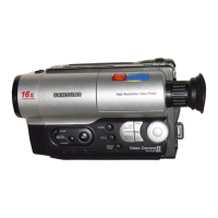
Samsung VP-A12 Specifications

General IconGeneral
Camcorder typeAnalog
Optical Zoom12x
Digital Zoom48x
Image SensorCCD
Recording MediaVHS-C
Image Sensor Size1/4 inch
Battery TypeRechargeable battery pack

Summary

Precautions

Product Specifications and Comparison Chart

Product Specifications

Detailed technical specifications for the camcorder models.

Comparison Chart

Compares features across different camcorder models (VP-A12/15 vs VP-A17/18).

Disassembly and Reassembly

Cabinet Disassembly

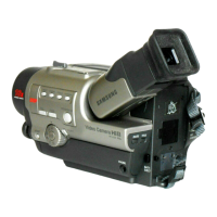
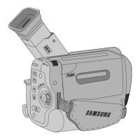
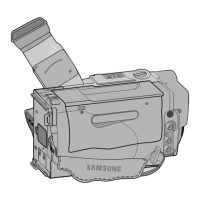
Step-by-step instructions for removing external cabinet parts.

Alignment and Adjustment

Mechanical Adjustment

Procedures for adjusting mechanical components and settings.

Camera Section Adjustment

Steps for calibrating camera functions like focus, white balance, and color.

VCR Section Adjustment

Procedures for aligning and adjusting the VCR playback and recording functions.

Exploded View and Parts List

Cabinet Assembly (1)

Exploded view and part list for the main cabinet components.

Mechanical Parts (1)

Exploded views and part lists for mechanical sub-assemblies.

Block Diagrams

Overall Block Diagram (Camera)

High-level overview of the camcorder's camera section circuitry.

Overall Block Diagram (VCR)

High-level overview of the camcorder's VCR section circuitry.

Video Playback

Block diagram for the video playback signal path.

Video Record

Block diagram for the video recording signal path.

Camera Main/CCD

Block diagram of the main camera processing and CCD interface.

Schematic Diagrams

Block Identification of Main PCB

Identifies major functional blocks on the main PCB layout.

Related product manuals