Do you have a question about the Samsung VP-A55 and is the answer not in the manual?
Essential safety guidelines and warnings for servicing the camcorder.
Details on servicing jigs, special tools, and extension/TP board connections.
Technical specifications and feature comparison for different camcorder models.
Step-by-step instructions for safely disassembling and reassembling the camcorder.
Procedures for calibrating and adjusting camera, VCR, and other sections.
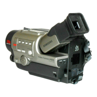
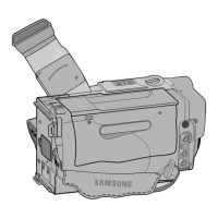
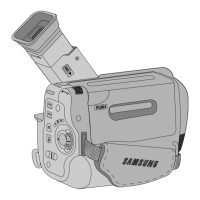
Visual diagrams and lists of parts for various assemblies to aid identification.
Comprehensive list of electrical components, including part numbers and specifications.
Functional block diagrams illustrating the camcorder's internal systems.
Layout diagrams for the main printed circuit boards (PCBs).
Diagrams showing the electrical connections between different boards.
Detailed circuit diagrams for various sections of the camcorder.
| Camcorder Media Type | MiniDV |
|---|---|
| Digital Zoom | 900x |
| Image Sensor Size | 1/6 inch |
| Focus Adjustment | Auto/Manual |
| White Balance | Auto/Manual |
| Microphone | Built-in |
| Viewfinder Type | Electronic |
| Screen Size | 2.5 inch |
| LCD Screen | Yes |
| Still Image Resolution | 640 x 480 |
| Battery Type | Lithium-Ion |
| Connector Type | USB, FireWire (IEEE 1394) |
| Effective Pixels | 680k |
| Video Recording Format | DV |
| Interface | USB |