Do you have a question about the Samsung VP-A57 and is the answer not in the manual?
Safety guidelines and essential precautions before servicing the camcorder.
Details on servicing jigs, special tools, IC blocks, and circuit board connections.
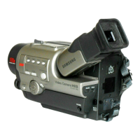
Technical details and comparison of camcorder models.
Step-by-step instructions for disassembling and reassembling camcorder components.
Procedures for mechanical adjustments as per the mechanical manual.
Procedures for adjusting camera settings including EVF, CVF, focus, white balance, and color.
Detailed steps for adjusting the VCR section, including video, audio, and timing parameters.
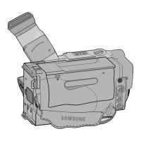
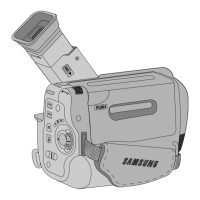
Exploded diagrams and part numbers for cabinet, mechanical, EVF, and CVF assemblies.
Comprehensive list of all electrical components, including resistors, capacitors, and ICs.
Functional block diagrams illustrating the camcorder's internal systems and interconnections.
Layout diagrams for the main and other printed circuit boards (component and conductor sides).
Diagrams showing the electrical connections between different boards and units.
Detailed electronic schematics for main PCB and functional blocks like Video, Audio, and Camera.
| Recording Format | VHS-C |
|---|---|
| Viewfinder | Color |
| Image Sensor | CCD |
| LCD Screen | 2.5 inches |
| Interface | Composite Video Output |