Do you have a question about the Samsung VP-D361i and is the answer not in the manual?
Safety precautions for servicing to prevent shock hazards and ensure proper device installation.
Guidelines for servicing, component replacement, and insulation checking procedures.
Techniques to reduce component damage from static electricity when handling sensitive devices.
Detailed specifications for video signal, system, LCD, connectors, and general features.
Comparison of specifications for VP-D353(Dragon-1) and VP-D363(Dragon-2) models.
Lists optional accessories and their part numbers, including battery packs and adapters.
Preparation and procedure for adjusting VCR settings like SWP Position.
Steps for adjusting camera system parameters like Zoom Track, Auto Hall, and White Balance.
Procedures for deck maintenance, including cleaning and periodic checks.
Step-by-step instructions for removing front, left, rear, and lens assemblies.
Procedures for loading/unloading mechanical modes and disassembling/reassembling housing ass'y.
Exploded view and parts list for the main chassis of VP-D361 series camcorders.
Exploded view and parts list for the main chassis of VP-D362/D363 series camcorders.
Exploded view and parts list for the main chassis of VP-D364W/D365W series camcorders.
Comprehensive list of electrical components for VP-D361 series camcorders.
Comprehensive list of electrical components for VP-D362/D363 series camcorders.
Comprehensive list of electrical components for VP-D364W/D365W series camcorders.
Overall block diagram illustrating the system structure of the digital camcorder.
Block diagram for IC101, likely a key component in the system.
Block diagram detailing the S5C7377X IC, a crucial part of the camcorder's processing.
Component layout diagram for the main printed circuit board.
Component layout diagram for the left side printed circuit board.
Component layout diagram for the LCD printed circuit board.
Component layout diagram for the rear printed circuit board.
Schematic diagram for the Arm Memory circuit on the main PCB.
Schematic diagram illustrating the audio processing circuit on the main PCB.
Schematic diagram for the built-in memory section on the main PCB.
Schematic diagram showing the CDS zoom motor circuit on the main PCB.
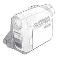
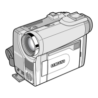
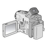
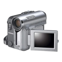
Overview of the camcorder's front and left side controls and features.
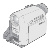
Overview of the camcorder's right and top side controls and features.
Description of the remote control buttons and their functions for specific models.
Instructions for installing the internal clock and remote control lithium batteries.
Flowchart for diagnosing and resolving loading issues in the camcorder.
Troubleshooting steps for issues where the camcorder's drum fails to rotate.
Troubleshooting steps for issues where the camcorder's capstan fails to rotate.
Diagnostic flowchart for reel-related emergencies and motor issues.
Overview and purpose of the document in relation to system design and hardware/software plans.
General definition and key features of the digital camcorder, including signals and interfaces.
Details on operating conditions, storage, DVC battery format, and sector arrangement.
Nomenclature for the top view of the deck assembly, identifying key mechanical parts.
Explanation of USB and IEEE 1394 interfaces, their advantages, and disadvantages.
Descriptions and specifications for various memory card types like CompactFlash, SD, and Memory Stick.
Table describing OSD display items, their function descriptions, and activation conditions.
| Recording Media | MiniDV |
|---|---|
| Image Sensor | 1/6" CCD |
| Optical Zoom | 34x |
| Focus Adjustment | Auto/Manual |
| Min Illumination | 2 lux |
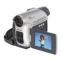
| Display Type | LCD |
| Microphone Operation Mode | Stereo |
| Battery Type | Lithium-Ion |
| Video Signal | PAL |
| Microphone | Built-in |
| Type | Camcorder |
| LCD Screen | 2.5 inches |
| Image Stabilizer | Electronic |
| Shooting Programs | Auto, Sports, Portrait, Spotlight, Sand & Snow, Night |
| Connector Type | USB, FireWire |
| Effective Pixels | 680, 000 |
| Focus | Auto/Manual |