EasyManua.ls Logo

Samsung VP-D362 User Manual

Samsung VP-D362
254 pages
To Next Page IconTo Next Page
Page #1 background imageLoading...
Page #1 background image
DIGITAL VIDEO CAMCORDER
Chassis : Dragon II
BASIC : VP-D363
Application Models
: VP-D361(i)/D361W(i)/D362(i)/
D363(i)/D364W(i)/D365W(i)
Application Area
:
XEF, XEU, XEG, XET, XEV, XEC, XSA, CDM,
XST, XEO, XEH, XEP, XEE, EAP, EUR, XEN,
HACO, TAW, TIT, COL, SEO, XSS, SED, XSH,
XSG, FES, XTL, CHN, ZAM, STS, SMR, XFA,
ITN, KNT, XSE, FPT, RAD, AFR, AND, UMG
MEA, SEA
SERVICE
Œ Shooting & compact Design
´ Use Built-in Flash Memory
ˇ Multi Memory Card Slot
¨ Direct Print System : PictBridge
TM
ˆ LED Light
Ø High quality MPEG4
Still image Interpolation
Real Wide mode (16:9)/WIDE LCD
33X ZOOM
˝ USB 2.0 Streaming
Manual
DIGITAL VIDEO CAMCORDER Merit & Character regarding Product
SERVICE MANUAL
VP-D361(i)/D361W(i)/D362(i)/D363(i)/D364W(i)/D365W(i)
ELECTRONICS
© Samsung Electronics Co., Ltd. FEB. 2006
Printed in Korea
AD82-00152A
This Service Manual is a property of Samsung Electronics Co .,Ltd.
Any unauthorized use of Manual can be punished under applicable
International and/or domestic law.

Table of Contents

Question and Answer IconNeed help?

Do you have a question about the Samsung VP-D362 and is the answer not in the manual?

Samsung VP-D362 Specifications

General IconGeneral
BrandSamsung
ModelVP-D362
CategoryCamcorder
LanguageEnglish

Summary

Precautions

1-1 Safety Precautions

Guidelines for ensuring instrument safety before returning to customer.

1-2 Servicing Precautions

Rules to follow for safe and correct servicing procedures, including component replacement.

1-3 ESD Precautions

Techniques to prevent damage to sensitive electronic components from static electricity.

Product Specification

2-1 Product Specification

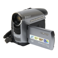
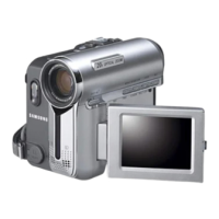
Detailed technical specifications for the camcorder including system, display, and general features.

Alignment and Adjustment

3-1 VCR Adjustment

Procedures for adjusting VCR functions, including preparation and specific settings.

3-2 Camera Adjustment

Steps for adjusting camera system parameters like zoom, white balance, and iris.

3-3 Deck Adjustment

Maintenance and adjustment procedures for the tape deck mechanism.

Disassembly and Reassembly

Electrical Parts List

Schematic Diagrams

10-1 Arm Memory (Main PCB)

Schematic diagram for the arm memory circuit on the main PCB.

10-2 Audio (Main PCB)

Schematic diagram for the audio circuit on the main PCB.

Operating Instructions

Initial Setting : System Menu Setting

Procedures for initial system setup, including clock, remote control, beep sound, and shutter sound settings.

Initial Setting : Display Menu Setting

Instructions for adjusting LCD screen settings and date/time display.

Troubleshooting

VIDEO MISSING IN DVC CAMERA

Troubleshooting steps for issues related to missing video signals in the DVC camera.

NO AUDIO OUTPUT

Troubleshooting steps for problems related to no audio output from the camcorder.

NO POWER

Troubleshooting steps for issues where the camcorder does not power on.

Circuit Operating Description

Reference Information

Related product manuals