EasyManua.ls Logo

Samsung VP-L350 User Manual

Samsung VP-L350
136 pages
To Next Page IconTo Next Page
Page #1 background imageLoading...
Page #1 background image
© Samsung Electronics Co.,Ltd. MAR. 1999
Printed in Korea
AD68-00079B
SERVICE MANUAL
SCL300/L310/L320/L330/L350/L800/L850/VP-L300/L320/L330/L350/L980
8mm CAMCORDER
SCL300/L310/L320/L330/L350
SCL800/L850
VP-L300/L320/L330/L350
VP-L980
SERVICE
1. Precautions
2. Service Tips
3. Product Specifications and
Comparison Chart
4. Disassembly and Reassem
5. Alignment and Adjustment
6. Exploded View and Parts L
7. Electrical Parts List
8. PCB Diagrams
9. Wiring Diagram
10. Schematic Diagrams
Manua
8mm CAMCORDER
CONTENTS
For mechanical disassembly and adjustment, refer to the “Mechanical Manual”
(DE-6 AD68-30200A).
cover 5/11/95 9:42 AM Page 1
Question and Answer IconNeed help?

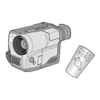
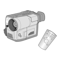
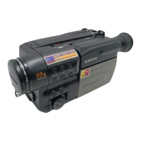
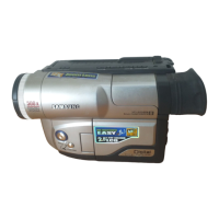
Do you have a question about the Samsung VP-L350 and is the answer not in the manual?

Samsung VP-L350 Specifications

General IconGeneral
BrandSamsung
ModelVP-L350
CategoryCamcorder
LanguageEnglish

Summary

Precautions

Safety Precautions

Essential safety guidelines to follow during operation and servicing.

Handling Static Sensitive Devices

Techniques to reduce damage from static electricity to components.

Service Tip

Video Light Bulb Replacement

Step-by-step instructions for replacing the video light bulb.

Product Specifications and Comparison Chart

NTSC Models Specifications

Detailed technical specifications for NTSC camcorder models.

PAL Models Specifications

Detailed technical specifications for PAL camcorder models.

Model Comparison Chart

Feature comparison across various NTSC and PAL camcorder models.

Disassembly and Reassembly

Cabinet Disassembly Procedures

General guide for disassembling the camcorder cabinet.

Component Removal Steps

Specific steps for removing major assemblies like case top, front, and LCD.

PCB Locations and Diagrams

Diagrams showing the location of circuit boards and connector layouts.

Alignment and Adjustment

Mechanism and Camera Alignment

Procedures for mechanism and camera section adjustments.

EVF and LCD Adjustments

Steps for adjusting the Electronic Viewfinder and LCD display.

VCR Section Adjustments

Detailed procedures for adjusting various VCR playback and recording functions.

Exploded View and Parts List

Cabinet Assemblies Parts List

Exploded views and parts lists for different cabinet assemblies.

Mechanical Parts Lists

Exploded views and parts lists for mechanical components.

EVF Assembly Parts List

Exploded view and parts list for the EVF assembly.

Electrical Parts List

PCB Component Lists

Comprehensive lists of electrical components for various PCB assemblies.

PCB Diagrams

Main PCB Diagrams (8mm & Hi-8)

Component and conductor layouts for Main PCBs (8mm and Hi-8).

Other PCB Layouts

Component and conductor layouts for Rear, Front, LCD, EVF, CCD, and Function PCBs.

Wring Diagram

Schematic Diagrams

Main Circuit Schematics

Schematic diagrams for main circuits like DC/DC, System Control, Video, Audio, and Camera.

Peripheral Circuit Schematics

Schematic diagrams for Rear, CCD, LCD, EVF, Front, and Function PCBs.

Related product manuals