EasyManua.ls Logo

Samsung WF393 Series - User Manual

Samsung WF393 Series
9 pages
Print Icon
To Next Page IconTo Next Page
Loading...
Fast Track Troubleshooting
Model: WF393**
Publication #Dr WF393 Production Date 4/29/14
IMPORTANT SAFETY NOTICE “For Technicians Only” This service data sheet is
intended for use by persons having electrical, electronic, and mechanical experience and knowledge
at a level generally considered acceptable in the appliance repair trade. Any attempt to repair a
major appliance may result in personal injury and property damage. The manufacturer or seller
cannot be responsible, nor assume any liability for injury or damage of any kind arising from the use
of this data sheet.
Bulletins:
Support Information:
HELP: 1-888-751-4086 (Tech Sup. ASC/SSD) - 1-866-894-0637 (Tech Sup. - FE/ME)
GSPN: http://gspn3.samsungcsportal.com/main.jsp
PLUS ONE: http://my.plus1solutions.net/clientPortals/samsung
**With the Power On**
**Test Mode** With the Power Off
SERVICE MODE: WITH POWER ON - PRESS: Signal + Extra Rinse
TEST FUNCTION PRESS
1 Cycle Count SIGNAL
2 Version SOIL Level
3
Board Input Test (Move Jog
dial to check LED) (See Chart
at bottom)
Extra Rinse
4
DIAGNOSTIC ERROR CODE
CHECK (See Below)
SPIN - (“d” will start flashing) Turn dial
either clockwise (c.w) or counter c.w.
5
SPIN TEST ( RPM) (ref:
NB***)
Pre Wash + Soil Level for 3sec. (To Pause:
press - START/PAUSE)
QUICK TEST MODE: WITH POWER OFF - PRESS: SOIL + SPIN + POWER
NB*** Spin Test will NOT test Hall Sensor in this mode. NOTE: ALWAYS
remember to offset counter weight when spin testing an empty machine
FACT: It is NORMAL for this unit to be unbalanced until 350-400 RPM
counter weights will only align correctly after this RPM is reached
Activate the SERVICE MODE first (ref: above).
Press the SPIN key to start DIAGNOSTIC CODE check mode. “d” will start flashing.
To cycle through the diagnostic codes (d1, d2, d3, etc.), turn the rotary cycle selector
(knob) either clockwise or counter clockwise.
When turning the rotary selector key (knob) in one direction, it shows diagnostic codes
from the latest (d1).
Now when turning the knob in the opposite direction it shows the diagnostic codes in the
reverse order. E.g. When it stops at “d5” and then turn backwards, it shows from “d4” to
“d”. (Refer to Diag. Code interpretation).
Service mode Option 4:
DIAGNOSTIC ERROR CODE CHECK
Use the Board input test under service mode to test water temp,
during normal wash operation.
Service mode Option 3:
Board Input Test Chart
TEST FUNCTION PRESS
1 Water Valve Test
TEMP
**Door Lock Must be Activated 1
st
before running Component **
2 Door Lock SPIN
3 Heater SOIL
4 Drain Pump /Bubble Pump SIGNAL
5 EEPROM MEMORY CLEAR
DELAY START + POWER (with POWER OFF)
Question and Answer IconNeed help?

Do you have a question about the Samsung WF393 Series and is the answer not in the manual?

Summary

Troubleshooting Modes

Quick Test Mode (Power Off)

Procedure to enter and use Quick Test Mode when the appliance is powered off.

Service Mode (Power On)

Procedure to enter and use Service Mode when the appliance is powered on.

Service Mode Options

Details on Board Input Test Chart and Diagnostic Error Code Check.

Component Testing Procedures

Door Lock Switch Testing

Steps to check the resistance and connections of the door lock switch.

Water Level Sensor Testing

Steps to check the frequency and connections of the water level sensor.

Water Valve Testing

Steps to check water valve resistance, diaphragm, and voltage.

Motor Resistance Testing

Checks resistance for drain and drum motors.

Common Error Code Analysis

Water Level Sensor Errors (LE)

Analysis of LE error code, including causes and corrective actions.

Motor and Hall Sensor Errors (3 E, E3, bE)

Analysis of motor-related errors (3E, E3, bE), causes, and fixes.

Water Supply Errors (nF, nF1)

Analysis of water supply errors (nF, nF1), causes, and corrective actions.

Drain Errors (nd)

Analysis of drain errors (nd), including causes and corrective actions.

Additional Error Code Analysis

Communication and Switch Errors

Analysis of communication and switch errors, including causes and fixes.

Door Operation Errors (dS, dL, LO, FL)

Analysis of door operation errors, causes, and corrective actions.

Heater and Water Leakage Errors

Analysis of heater and water leakage errors, causes, and fixes.

Further Error Code Analysis

Overflow and Temperature Sensor Errors

Analysis of overflow (OE) and temperature sensor (tE) errors.

Unbalance Load Errors (dc)

Analysis of unbalance load errors (dc), causes, and corrective actions.

Advanced Error Codes

Clutch and Foaming Errors

Analysis of clutch motor, hall sensor, and foaming detection errors.

PBA and System Errors

Analysis of Mems PBA and System errors, including causes and fixes.

Troubleshooting Common Problems

Door Lock and Spin Issues

Troubleshooting for door lock failure and inability to spin.

Operation and Noise Issues

Troubleshooting for no key operation, stopping, and noise problems.

Water and Drainage Issues

Troubleshooting for water filling, leakage, and drainage problems.

Load and Detergent Issues

Troubleshooting for load balance, wetness, and detergent issues.

Water Supply Issues

Troubleshooting for no water or insufficient water supply.

PCB Component Identification

Sub PCB Layout and Connectors

Identifies components and connectors on the Sub PCB.

Main PCB Layout and Connectors

Identifies components and connectors on the Main PCB.

Wiring and Schematic Information

Wire Color Reference

Provides a reference for wire colors used in the diagrams.

Schematic Diagram Overview

Shows the overall schematic wiring diagram of the appliance.

Overview

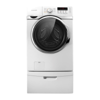
This document provides a comprehensive guide for the Samsung WF393** washing machine, covering its operation, troubleshooting, and maintenance.

Function Description

The Samsung WF393** is a washing machine designed for household use, featuring various wash cycles and options to cater to different laundry needs. It incorporates a range of sensors and control systems to ensure efficient and safe operation. The machine offers both quick test modes for diagnostics and a service mode for in-depth troubleshooting and component checks.

Important Technical Specifications

  • Water Valve Resistance: 1.0K to 1.2K ohms.
  • Door Lock Switch Resistance: Approximately 40 to 57Ω between No.1 and No.3 pins.
  • Water Level Sensor Frequency: Approximately 26.4 kHz with no load.
  • Drain Motor Resistance: Approximately 174Ω between the terminals for the Water Supply Valve.
  • Drum Motor Resistance: 15Ω between any two of the three terminals.
  • Washing Motor Resistance (DD Motor): 2 to 4 MΩ between pins 1 and 3, and 1 and 4 of the four (4) pins on the main PCB motor.
  • Washing Motor Resistance (Universal Motor): Approximately 40 to 45Ω between Nos. 1 and 4 of the wire pin on the side of the TACHO SENSOR.
  • Washing Motor Resistance (Three Phase Motor): Approximately 3 to 12V between Nos. 2 and 3 of the wire pin on the side of the HALL SENSOR (voltages may differ depending on the speed of revolutions).
  • Water Supply Valve Resistance (nF/nF1 error): 0.8k to 1.8KΩ between the terminals.
  • Drain Pump Resistance (nd error): Drain: 13.50 ~ 16.50Ω; Bubble: 18.750 ~ 22.750Ω.
  • Door Switch Resistance (dL error - Type 1): Approximately 125Ω between 1 and 3 Pin.
  • Door Lock Switch Resistance (dL error - Type 2): Approximately 949Ω between Nos. 3 and 5.
  • Washing Heater Resistance (Hr error - Type 1): 16.05±0.65Ω between A and B.
  • Water Valve Coil Resistance (No water/not enough water error): 1.18K ohms.

Usage Features

The washing machine offers a user-friendly interface with various modes and options:

  • Quick Test Mode (Power Off): Activated by pressing SOIL + SPIN + POWER. This mode allows for quick checks of individual components:
    • Water Valve Test: Checks water valve operation.
    • Door Lock: Verifies door lock functionality (requires activation before running other components).
    • Heater: Tests the heating element.
    • Drain Pump/Bubble Pump: Checks pump operation.
    • EEPROM Memory Clear: Clears memory by pressing DELAY START + POWER.
  • Service Mode (Power On): Activated by pressing SIGNAL + EXTRA RINSE. This mode provides more in-depth diagnostics:
    • Cycle Count/Version: Displays the number of cycles completed and software version.
    • Board Input Test: Allows checking LED indicators by moving the jog dial. This is useful for testing water temperature during normal wash operation.
    • Diagnostic Error Code Check: Activated by pressing SPIN. "d" will flash, and turning the rotary cycle selector (knob) clockwise or counter-clockwise cycles through diagnostic codes (d1, d2, d3, etc.). Turning the knob in one direction shows codes from the latest (d1), while turning in the opposite direction shows codes in reverse order (e.g., d5 to d4).
    • Spin Test (RPM): Activated by pressing SPIN ("d" will flash). Turning the dial clockwise or counter-clockwise initiates the spin test. Note that this test does not check the Hall Sensor and requires offsetting the counterweight when testing an empty machine. The unit is normally unbalanced until 350-400 RPM, as counterweights align correctly only after this RPM is reached.
    • Pre Wash + Soil Level (for 3 seconds): Used to pause the cycle.

Maintenance Features

The manual provides detailed instructions for checking and correcting various issues, including:

  • Component Checks:
    • Door Lock S/W: Check resistance before and after power-off.
    • Water Level Sensor: Check frequency and connections.
    • Water Valve: Check resistance, foreign material in diaphragm, and voltage (110V) during "water valve test."
    • Drain Motor: Check resistance between terminals.
    • Drum Motor: Plug out connector and read resistances between any two of the three terminals.
  • Error Mode Troubleshooting: The document lists various error codes (LE, 3E/E3/bE, nF/nF1, nd, dS, dL, LO, FL, Hr, tE, dc, OE, PE, PEI, SUdS/Sd, 8E1/8E2/8E, SF1/SF2/SF3) with their causes, corrective actions, and descriptions, often accompanied by photos.
    • Water Level Sensor (LE): Check terminal connections, sensor replacement, and PBA replacement.
    • Washing Motor/Hall Sensor (3E/E3/bE): Check motor connector, Hall sensor, stator, and PBA control circuit.
    • Water Supply (nF/nF1): Check wire connections, foreign material in valve, freezing, and PBA relay.
    • Drain (nd): Check drain pump, foreign materials, freezing, and PCB.
    • Communication Error: Check wire connections between sub and main PBAs, and PBA communication circuit.
    • Switch Error (E2/Sr): Check for stuck buttons, tight holding screws, and main PBA switching IC.
    • Door Error (dS/dL/LO/FL): Check door status, door switch, drain pump, dry duct fan motor, and main PBA door sensing circuit.
    • Heater Error (Hr): Check washing heater, dry heater, steam heater, and temperature sensors.
    • Water Leakage (LE): Check for leaks on base, hoses, valves, tub connections, foreign material in DV case, and drain motor operation.
    • Overflow (OE): Check water level sensor, hose, and freezing.
    • Temperature Sensor (tE): Check washing/dry/duct temperature sensors and connections.
    • Unbalance (dc): Check laundry type and load distribution.
    • Clutch Motor Error (PE): Check clutch motor, assembly status, and wire connector terminals.
    • Clutch Hall Sensor Error (PEI): Check clutch hall sensor, wire connector terminals, clutch switching status, and coupling assembly.
    • Foaming Detected (SUdS/Sd): Normal operation, indicates excessive foaming.
    • Mems PBA Error (8E1/8E2/8E): Check wire connections and replace Mems PBA if necessary.
    • System Error (SF1/SF2/SF3): Micro Controller Operation Fail, replace Assy PCB.
  • General Troubleshooting: The manual also addresses common problems like "Will Not Lock," "Will Not Spin," "No Key Operation," "Excessive Suds," "Will Not Unlock," "Fills with wrong temperature water," "Will Not Start," "Stops," "Leaks water," "Vibrates or is too noisy," "Load is too wet at the End of the cycle," "Has detergent remains In the automatic dispenser After the wash cycle is complete," and "Has no water Or not enough water," providing step-by-step corrective actions.
  • Schematic Diagram: A detailed schematic diagram (POTOMAC) is provided, illustrating the connections between the main PCB, sub PCB, motor, sensors, valves, and other components, along with a color code reference. This is crucial for electrical diagnostics and component identification.
  • PCB Pinouts: Detailed pinout descriptions for the Sub PCB (CN10, CN3_GRAPHIC, CN2) and Main PCB (CN6, CN1, CN7, CN5, CN3, CN4, CN10) are included, aiding in precise voltage and signal checks.

This comprehensive guide is intended for qualified technicians to diagnose and repair the Samsung WF393** washing machine safely and effectively.

Samsung WF393 Series Specifications

General IconGeneral
BrandSamsung
ModelWF393 Series
CategoryWasher
LanguageEnglish

Related product manuals