EasyManua.ls Logo

Samsung WSM520V - User Manual

Samsung WSM520V
8 pages
Print Icon
To Next Page IconTo Next Page
Loading...
WSM520V
Version 1.0 Samsung Electronics page 1 of 8
User Manual
1. Introduction
The WSM520V module is wireless audio module based on AV5100. The AV5100 is 5GHz wireless audio
SoC (System-on-chip), optimized for building point to multi-point digital wireless audio solutions such as
wireless subwoofers, wireless rear speakers and in home theater system. The AV5100 contains all the
necessary radio transceiver and digital baseband circuitry to form a complete digital wireless node without the
need for external processing.
The WSM520V can be powered from a +5V supply input and the AV5100 contains all the necessary power
management and analog circuitry needed to operate the chip.
The WSM520V can operate in upper bands (5725~5825MHz) of 5GHz spectrum, enabling worldwide
coverage.
2. Feature
Product form factor
Module Size (mm): 40.0 (W) X 26.0 (L) X 3.0 (H)
PCB size (mm): 40.0 (W) X 2.6.0 (L) x 1.0 (H)
Shield can (mm): 24.7 (W) X 21.9 (L) X 2.0(H)
Antenna Type : PCB Printed Antenna
Question and Answer IconNeed help?

Do you have a question about the Samsung WSM520V and is the answer not in the manual?

Overview

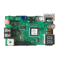
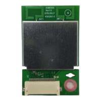
The WSM520V is a wireless audio module designed for integration into various home theater and audio systems, particularly for wireless subwoofers and rear speakers. It is based on the AV5100, a 5GHz wireless audio System-on-chip (SoC) optimized for point-to-multipoint digital wireless audio solutions. The module integrates all necessary radio transceiver and digital baseband circuitry, eliminating the need for external processing to form a complete digital wireless node.

Function Description:

The WSM520V module acts as a core component for wireless audio communication, enabling the transmission and reception of audio signals over a 5GHz spectrum. It supports both wireless subwoofer solutions and wireless 2.1 solutions. In a wireless subwoofer setup, the module facilitates communication between a soundbar (acting as an arbiter) and a subwoofer (acting as a client), transmitting mono audio at 96dB SNR and 5KHz. For wireless 2.1 solutions, the module supports stereo audio at 96dB SNR and 20KHz for rear speakers, and mono audio at 96dB SNR and 5KHz for a subwoofer, all communicating with a soundbar. The module's architecture includes a DSP and MCU for audio processing and control, connected via I2C and I2S interfaces.

Important Technical Specifications:

  • Product Form Factor:
    • Module Size: 40.0 (W) x 26.0 (L) x 3.0 (H) mm
    • PCB Size: 40.0 (W) x 26.0 (L) x 1.0 (H) mm
    • Shield Can: 24.7 (W) x 21.9 (L) x 2.0 (H) mm
    • Antenna Type: PCB Printed Antenna
  • Operating Conditions:
    • Supply Voltage (Vdc): 4.5V (Min), 5.0V (Typ), 5.5V (Max)
    • Supply Current (Idc): Up to 500mA
    • Operating Temperature: 5°C (Min), 35°C (Max)
  • RF Characteristics:
    • Modulation: Pi/4DQPSK / SSB
    • RF Frequency Range: 5725 – 5825 MHz (upper bands of 5GHz spectrum)
    • Bandwidth: 2 MHz
    • RF Frequency Channels:
      • Channel (0) LO: 5725, Fc: NOT USED
      • Channel (1) LO: 5727, Fc: NOT USED
      • Channel (2) LO: 5729, Fc: 5730.35
      • Channel (3) LO: 5731, Fc: 5732.35
      • Channel (4) LO: 5733, Fc: 5734.35
      • ...
      • Channel (45) LO: 5815, Fc: 5816.35
      • Channel (46) LO: 5817, Fc: 5818.35
      • Channel (47) LO: 5819, Fc: 5820.35
      • Channel (48) LO: 5821, Fc: NOT USED
      • Channel (49) LO: 5823, Fc: NOT USED
    • Diversity: 1TX / 2RX
    • Antenna Peak Gain: 2.2 dBi
    • RF TX Output Power (tolerance): 14.0 (+2dB) dBm
  • Audio Performance:
    • SNR: 96dB
    • Latency: Low, fixed latency (<20ms)
  • Connectivity:
    • 24-pin FPC connector for I/O interface
    • I2C serial clock slave/master
    • I2C serial data slave/master
    • I2S Left Light clock (WCLK)
    • I2S Bit clock (BCK)
    • I2S data lines (DAT 0, DAT 1, DAT 2)
    • USB digital audio capability
    • GPIO pins for general purpose I/O
    • External flash memory interface (MISO, MOSI, CS, SCLK)
  • Clock:
    • Main crystal frequency: 16MHz

Usage Features:

  • Complete VMX Wireless Audio Communication System: The module provides a comprehensive solution for wireless audio, simplifying integration into end products.
  • Worldwide Coverage: Operates in the upper bands of the 5GHz spectrum (5725-5825MHz), enabling broad geographical applicability.
  • Multiple OTA Audio Configuration: Supports various over-the-air audio configurations, offering flexibility for different audio setups.
  • Separate RF Transmit and Receive I/O: Dedicated paths for RF transmission and reception optimize performance.
  • RX Diversity: Enhances signal reception reliability by utilizing multiple receive antennas.
  • Digital Audio Interfaces: Includes USB and I2S digital audio capabilities for versatile audio input/output options.
  • Complete Power Management: The AV5100 SoC integrates all necessary power management and analog circuitry, simplifying power supply design for the module (requires a +5V supply input).
  • Transmit Mode: The audio engine converts audio data into packetized digital IQ signals, pulse-shapes them, and converts them to analog IQ inputs for the radio transceiver. A programmable baseband filter reduces RF spectrum side lobes and suppresses DAC image/spurious. Output power is programmable with close-loop TX power control via a power detector. The differential RF TX DA outputs connect to a power amplifier via a balun filter, and the amplified TX carrier signal is radiated by a printed antenna after passing through a Transmit/Receive switch.
  • Receive Mode: Supports antenna diversity. The T/R switch output connects to the differential RF LNA inputs in the AV5100 via a balun filter. The radio transceiver performs filtering and amplification, with gain controlled by the baseband. Analog IQ outputs are sampled by the baseband's dual-channel ADC, and the received data is demodulated and fed to the audio processing engine.

Maintenance Features:

  • FCC and IC Compliance: The module is designed to comply with FCC Part 15 rules and Canadian ICES-003, ensuring regulatory adherence for the end product.
  • OEM Integrator Responsibility: The OEM integrator is responsible for ensuring the end product's IC compliance and informing end-users about regulatory requirements.
  • User Manual Information: The end product's user manual must inform users about maintaining a minimum separation distance of 20cm between the antenna and the body during operation to satisfy RF exposure requirements. It must also include specific FCC and IC statements regarding interference and operation conditions.
  • Labeling Requirements: The final end product must be labeled with "Contains TX FCC ID: A3LWSM520V" in a visible area. If the product is larger than 8x10cm, the FCC Part 15.19 statement must also be on the label. For IC compliance, the label must include "Contains TX IC: 649E-WSM520V".
  • Modifications: Any changes or modifications not expressly approved by the manufacturer could void the user's authority to operate the equipment.

Samsung WSM520V Specifications

General IconGeneral
BrandSamsung
ModelWSM520V
CategoryControl Unit
LanguageEnglish

Related product manuals