Switch Control Setup
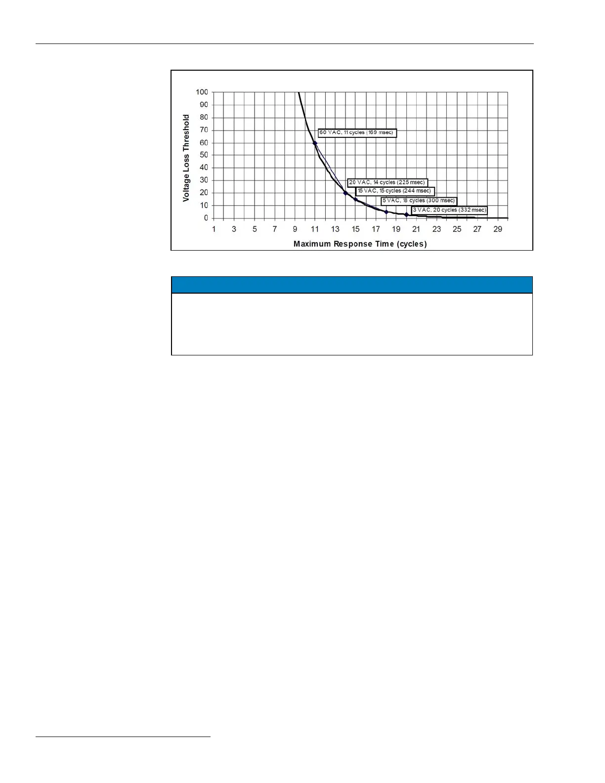
Figure 10. The Voltage Loss Threshold and Maximum Response Time curve.
NOTICE
Times listed in the Figure 10 curve do not include the output relay or switch
operation times. For proper coordination with a fast reclosing source-side
protective device, make sure the reclosing interval time for the device is long
enough for the switch control to detect the outage and for the sectionalizing switch
to open fully.
Backfeed from customer loads also affects the speed of voltage-loss detection. Enter
a threshold value high enough to detect the loss of voltage before service is resumed and
low enough to ensure loss of voltage is not falsely detected because of system overload
or persistent backfeed.
Voltage Sensors Present
Congure this setpoint for the number of sensors on the line switch. For S&C PME/PMH
pad-mounted switches, the IntelliLink Setup Software automatically sets the correct value
based on the Padmount Conguration status selected on the Setup>General>Sensor
Conguration screen. Correct values are also set by IntelliLink software for Vista
Underground Distribution Switchgear. (Default: Phase A, B and C)
Voltage Difference Checking (Vista switchgear only)
If Switch 1 and 2 are closed and their voltages disagree by greater than 10 volts, at least
one voltage sensor is generating bad voltage. When set to the Enabled mode, the control
will disable automatic operation while this condition is latched. The state is latched on
the rst occurrence of mismatched voltages. The latched state will be reset if the control
doesn’t sense a mismatched voltage, within the user-congured time period, or if reset
by disabling automatic operation from the faceplate or a SCADA command. The control
will indicate maintenance action is required with the General Maintenance-Dispatch
status point. The Logs-Status Point Log screen indicates the Cross-Switch Volt Imbal
Det status point is active and the Maintenance Required status point is active when
this feature is enabled and the condition is true. (Default: Disabled)
Stable Time Period to Reset (mins) (Vista only)
When voltages for Switch 1 and 2 disagree, according to the description for the previous
eld, the control will latch a Voltage-Mismatch state. This state will reset when the
control senses no mismatch voltage during this time period. (Range: 1 to 254 minutes
or Never; Step: 1; Default: 10)
Nominal Operating Frequency
Set this to the nominal operating frequency in Hertz for the distribution system. (Default:
60 Hz)
26 S&C Instruction Sheet 1045-530