2
GENERAL
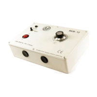
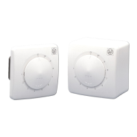
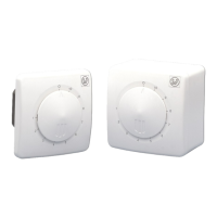
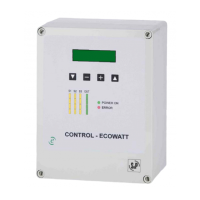
The controllers utilise triac cutting techniques. By adjustment of a rotary knob, the user may vary
the available voltage to the motors which have been approved by the manufacturer for speed
control by triac.
WARNING!
Mains voltage is present. It is the responsibility of the user to ensure compliance with the Health
and Safety at Work Act, 1974.
CAUTION
1. Isolate mains supply before connecting.
2. This unit must be earthed.
3. All electrical connections should be made by a qualified electrician.
4. All wiring must be in accordance with current wiring regulations. The control should be
provided with a separate double pole isolator switch.
SPECIFICATION
1. The controller is designed for continuous operation with the maximum rated current load
listed in table 1 at 40° C. ambient on single phase 230 Volts ~ 50Hz supply.
2. The normal equipment temperature range is -20°C to +40°C.
3. The unit meets the EMC requirements of EN 61800-3:1997 and EN61000-3:2006
4. The controller is housed in an enclosure that is suitable for the current rating and is IP42
rated.
Table 1
20mm ceramic 3.5 Amp “F” Type
20mm ceramic 5.0 Amp “F” Type
32mm ceramic 10.0 Amp “F” Type
20mm ceramic 10.0 Amp “F” Type
32mm ceramic 8.0 Amp “T” Type
32mm ceramic 10.0 Amp “T” Type
32mm ceramic 12.5 Amp “T” Type
32mm ceramic 16.0 Amp “T” Type
Note: - Fuses in the units are for protection of the controller wiring and components in case of short
circuit. They do not offer motor overload protection.