TR90-Series Due to continuing product development, specications are subject to change without notice. © 2018 S&P
132104_002 Revised 8/2018 Page 3
Exhaust & Outside Air Ducts
The Exhaust Air Duct and the Outside Air Duct connect the unit to
the outside. Flexible insulated duct is typically used. See Table
under “Duct Sizes” below.
DO NOT PLACE ANY STALE AIR RETURNS IN GARAGES.
Can an ERV be used to ventilate bathrooms?
A S&P ERV can be used as a central exhaust system in place of
bathroom exhaust fans. Tie a grill in each bathroom directly
back to the ERV – see Schematic (A). A successful installation
should provide at least 50 CFM of exhaust per moisture producing
bathroom. When used for bathroom exhaust, the TR90 should
be used for only one bathroom. Install a control in the bathroom
ventilated by the ERV (see Secondary Operating Controls, below).
For houses where radon is a concern:
The rst line of defense against radon should always be techniques
that prevent the entry of radon into the home, such as under-slab
suction, vented perimeter drainage, and crack sealing. However,
if moderate levels of radon continue to be present, it is important
that the unit slightly pressurize the basement, not de-pressurize
the basement.
Installation of this unit for radon mitigation is beyond the
scope of this manual. Consult a radon mitigation professional.
Duct Minimum Sizes and Type
Exhaust Air & Outside Air
(EA & OA)
6” round insulated duct
8” round insulated duct may be
used to maintain maximum airow
Fresh Air & Stale Air
(FA & RA)
6” round or 8” oval rigid
un-insulated
All ducts from unit to house in unconditioned spaces like
attics and crawl spaces MUST BE INSULATED.
Duct Sizes
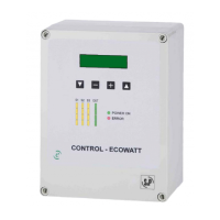
Controls
For an installation in which the ERV should run continuously in
order to provide the required ventilation rate for the home,
no controls are needed. However, in most installations, control
over the unit operation is desired and this is best provided by a
Proportional Timer.
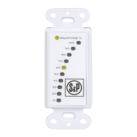
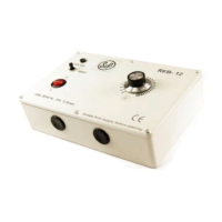
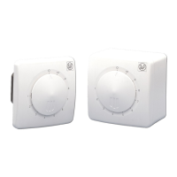
Proportional timers (SPTL or SFM controls for TR90 or line voltage
controls for TR90G) may be located anywhere that is convenient.
A typical location for either control is next to the home’s
thermostat. Proportional timers operate the ERV to provide
regular background ventilation of the home.
TR90 installations that pull stale air from specic rooms, such as
bathrooms, should have Push-Button Lighted (SPBL) Controls in
those rooms. The secondary operating controls allow the system
to be turned on from various locations in the house.
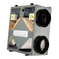
Mounting the Unit
Unit may be installed in any orientation:
Orient the unit for the simplest duct layout and connections.
Note however that the door is equipped with slide-o hinges. For
the homeowner’s convenience it is helpful to orient the unit so
that the door does not drop o when it is unlatched.
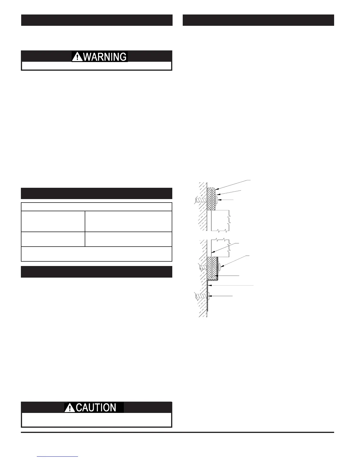
Mounting the TR90 on a concrete foundation wall:
Mount hanging bracket to the wall with appropriate concrete
anchors. Use pre-cut foam tape from small parts bag. Remove
backing and apply two pieces of foam tape equally spaced along
the unit’s mounting ange to be held by the hanging bracket. Apply
the other two pieces of foam over two holes that will be used for
fastening, on the other ange. The tape should be applied in a “U”
shape to cushion both the front and back of the integral anges.
Lift unit and slide unit ange into the hanging bracket. Using metal
at washers, fasten ange opposite hanging bracket to structure.
Safety screws should similarly be installed passing through the
hanging bracket and ange. Make sure the screws, which you must
supply, are properly selected for the loads and substrate involved.
Mounting the TR90 to a stud wall:
Mount unit using supplied hanging bracket kit as described for
mounting to concrete foundation wall. Note that the hole layout
on the integral mounting anges and the hanging bracket are
spaced for 16” on-center framing patterns.
Foam Tape
Foam Tape
Metal Washer
Lag Screw or Concrete Anchor
(provided by others)
Lag Screw or Concrete Anchor
(provided by others)
Unit Flange
Optional Washer and Screw
(provided by others)
Hanging Bracket
* TR90 only.
Suspending the TR90 from oor joists or trusses:
The unit may be screwed directly to joists or trusses using the
hanging bracket and integral ange. Mount as described for
mounting to concrete foundation wall. Note that the hole layout
on the hanging bracket is spaced for 16”on-center layouts.
Mounting the TR90G:
The TR90G can be mounted similar to the TR90 however, the
TR90G does not come with a hanging bracket. Using at washers
provided install screws through the holes in the anges of the
unit. Make sure the screws, which you must supply, are properly
selected for the loads and substrate involved.
RISK OF INJURY WHEN LIFTING UNIT AND INSTALLING UNIT
OVERHEAD. GET A HELPER AND WEAR EYE PROTECTION.
 Loading...