TR90-Series Due to continuing product development, specications are subject to change without notice. © 2018 S&P
132104_002 Revised 8/2018 Page 5
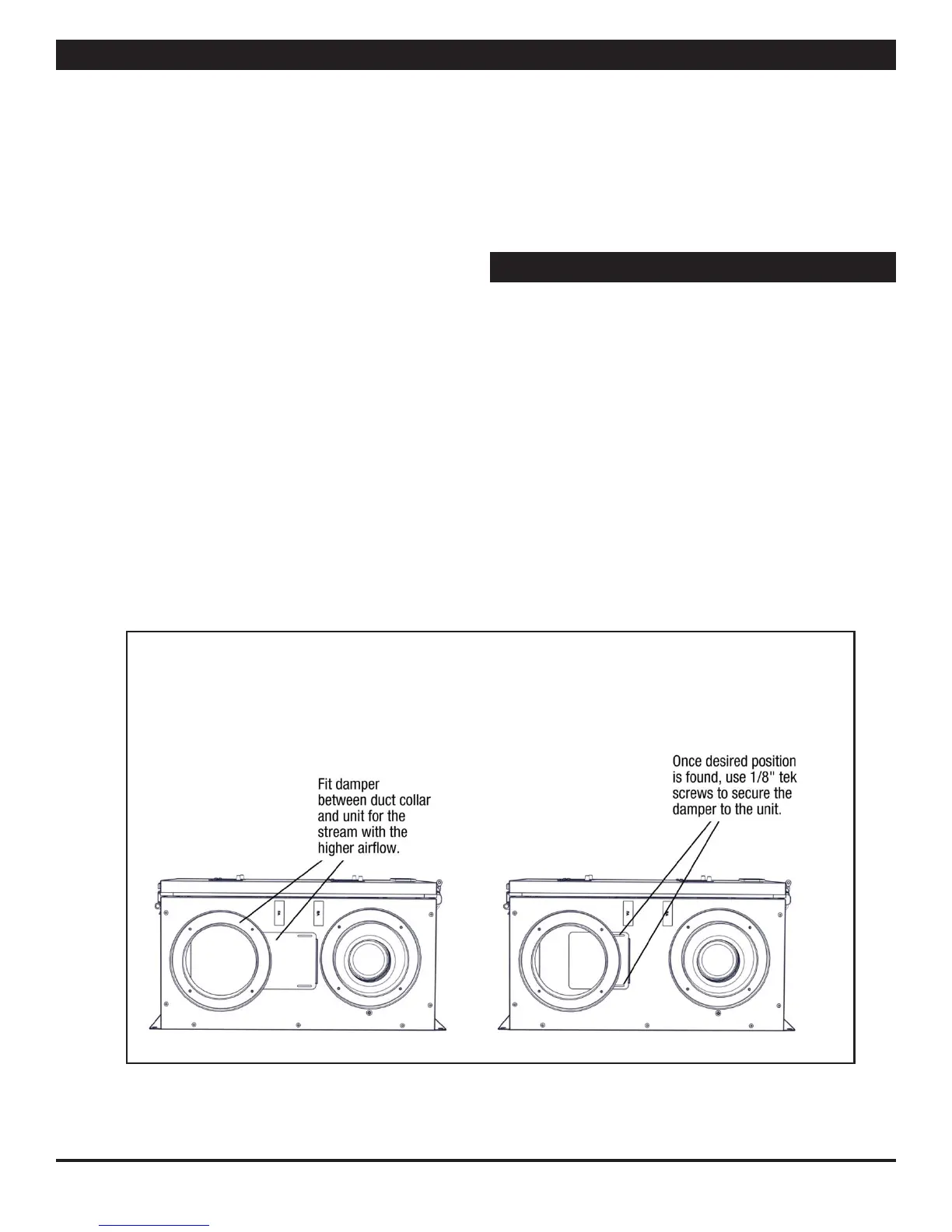
Damper Installation
www.renewaire.com (800) 627- 4499 support@renewaire.com
www.renewaire.com (800) 627- 4499 support@renewaire.com
Airow
Airow should be occurring in both airstreams. Sometimes the
easiest place to conrm that air is moving is at the external
wall caps.
If exact airow is critical, it may be desireable to permanently
install ow measuring stations and manometers. These can
also be used to determine when lters should be cleaned or
changed.
Use Static Taps to Measure Airow Rates
See “Cross Core Static Drop” in MEASURING AIRFLOW table on
Page 6.
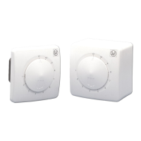
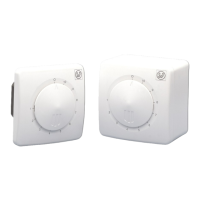
Use Damper to Balance Air Flow to Desired Rates, If
Necessary
The ERV’s blower motor are well suited for volume control by
dampers on the inlet of the units. One balancing damper is
provided in the units parts tray. NOTE: The unit is considered
balanced if the dierence between the two airows is not more
than 10 CFM.
After measuring the airow of the units, the balancing damper
may be used to blance airow if desired. Place the damper
between the duct collar and the unit for the outlet of the
airstream recording higher ow. NOTE: Install the damper so
that it slides in the space between the duct collars for the TR90
and the TR90G.
Verifying Unit Performance
Equipment Required
• A magnahelic gauge or other device capable of measuring 0
to 1.0 in. water of dierential pressure.
• 2 pieces of natural rubber latex tubing, 1/8” ID, 1/16” wall
works the best.
Slowly move the damper further into the duct until the desired
airow is recorded. Secure the damper in place using 1/8” tek
screws (provided). NOTE: Drilling through the case while the
unit is running may cause metal shards to be drawn into the
unit.
NOTE: be sure to remove cap from pressure port before
inserting tubing. Ensure tubing is well seated in pressure ports.
NOTE: The tubing should extend into the pressure port
approximately 1 inch.
Measuring Airow
 Loading...