TR90-Series Due to continuing product development, specications are subject to change without notice. © 2018 S&P
132104_002 Revised 9/2018 Page 6
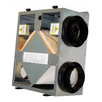
DIFFERENTIAL STATIC ACROSS CORE DSP VS. CFM
TR90, TR90G
DSP 0.10 0.20 0.30
Fresh Air (FA) CFM 42 84 127
Room Air (RA) CFM
42 84 127
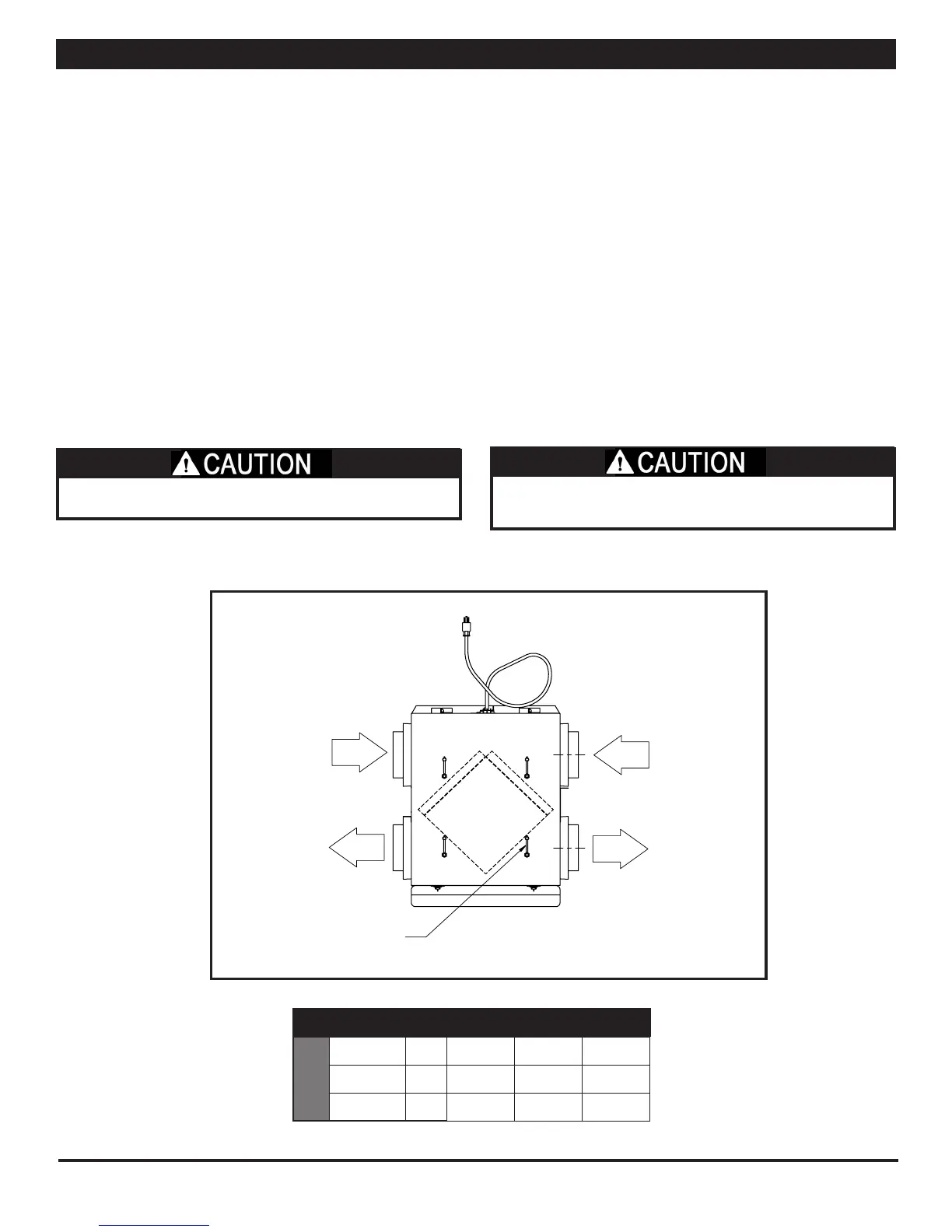
OA
EA
RA
FA
Pressure Ports
(4) Typ.
Model: EV90
Drawing Type: Airflow Diagram
Version: JAN18
The individual dierential static pressures (DP) are measured
using the installed pressure ports located in the front of the
units core access doors.
NOTE: These ports are carefully located on the unit to give the
most accurate airow measurement. Do not relocate pressure
ports.
• To read SCFM of Fresh Air (FA) install the “high” pressure
side (+) of your measuring device to the Outside Air (OA)
port and the “low” pressure side (-) to the Fresh Air (FA)
port.
• To read SCFM of Room Air (RA) install the “high” pressure
side (+) of your measuring device to the Room Aire (RA)
port and the “low” pressure side (-) to the Exhaust Air (EA)
port.
• If gauge drops below zero, reverse tubing connections.
• Use the reading displayed on your measurement device to
cross reference the CFM output using the conversion chart.
• Make sure clean lters are installed before balancing air
ow. Dirty or clogged lters reduce airow through the
unit.
• The proper airow range for the models are 40-110CFM
Cross Core Static Pressure Measurement Instructions
NOTE: Be sure to replace cap into pressure port when airow
measuring is completed.
NOTE: For best performance the airow rate for both the Fresh
Air and the Exhaust Air should be roughly equal (“balanced”).
In some facilities a slight positive or negative pressure in
the building is desired. TR energy recovery ventilators can
generally operate with a ow imbalance of up to 20% without
signicant loss in energy recovery eciency.
 Loading...