2
4
Installation Guide:
Health & Safety
This unit must be installed by a suitably qualified person in accordance with the latest IEE Wiring
Regulations.
Isolate mains supply before commencing installation. Please read all installation instructions before
proceeding.
Example circuit diagrams for typical installations are shown. These diagrams are schematic and should
be used as a guide only. Please ensure that all installations comply with the current IEE regulations. For
reasons of space and clarity not every system has been included and the diagrams have been simplified,
for instance some Earth connections have been omitted. Other control components shown in the
diagrams i.e. Valves, Room Stats etc. are general representations only. However, the wiring detail can
be applied to the corresponding models of most manufacturers.
Your product is not user serviceable. Do not dismantle this product.
Due to our policy of continuous product improvement and development, the specifications in this guide
may be subject to change without prior notice.
Elite Security Products
Unit 7, Target Park, Shawbank Road,
Lakeside, Redditch, B98 8YN
Tel: 01527 515150
Fax: 01527 515143
Email: info@espuk.com
Web: www.espuk.com
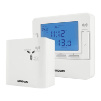
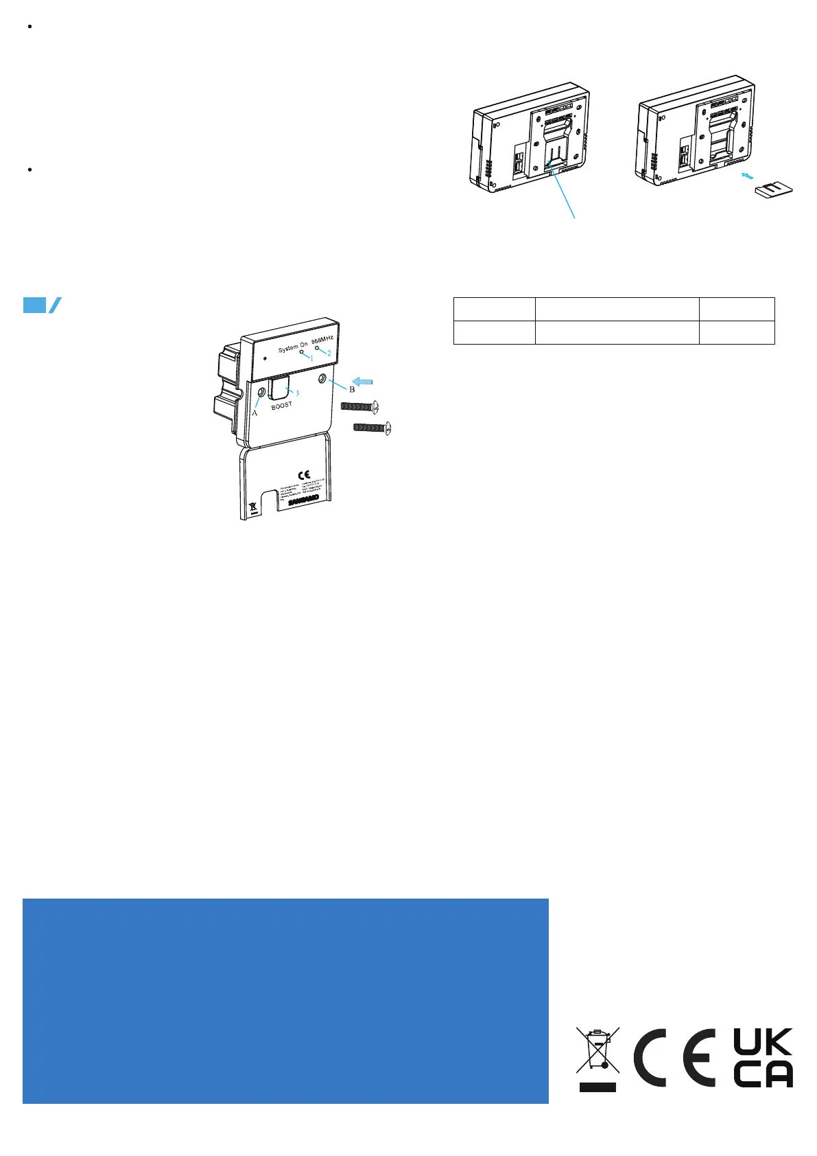
4.1 There are
three easy steps
for installation of the receiver:
Step one: Flip down the front
plate;
Step two: Wiring according to the
diagram and the labelled ports of
the switch; and
Step three: Install the switch in
the wall or mounting box with
screws (as shown in Fig.3 )
When cutting the aperture for the
output flexible cord, ensure no
sharp edges remain.
4.2 There are two easy steps to fix the stand.
Fig.3
1. This LED indicates if a signal is being sent to the boiler to turn on.
Blue light indicates the boiler should be firing.
2. If LED is permanently lit, no RF signal is being found.Heating will
turn off after 10 minutes,if no RF transmission resumes. After the RF
signal is recognized the heating schedule will continue.
3. Manual button. If RF signal fails, for example if the batteries in the
thermostat are flat,this button can turn the heating on and off.
pull upward to take out the stand
Fix the stand according
to the above diagram.
Date Issued
J20 A30-CHPRSTATDPRF-01-2 Rev.1
Issue No Description
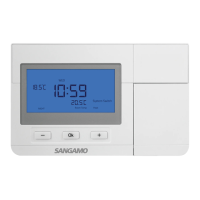
Optimum Start/Delayed Start: The default setting is optimum start.
When this mode is selected, you set the time you want to be warm and
Optimum Start will do the rest. On warmer days it will start later.
Optimum Start ensures that you are warm when you want to be (and not
before), reducing wasted energy and saving money.
When delayed start has been selected, You set the earliest start time,
based on an estimate and Delayed Start will do the rest. Delayed Start
will delay the boiler firing time on warmer days, when it is possible to
save energy.
Delayed Stop ON/ Delayed Stop OFF: The default setting is
Delayed stop OFF. When Delayed Stop is OFF, the thermostat will turn
off the heater as per hysteresis algorithm or TPI control normally.
When Delayed Stop is ON, the thermostat will calculate how long the
house will take to cool down , then turns off the boiler at the earliest
possible moment, when it calculates that the temperature will not decay
by more than 1/2℃
 Loading...