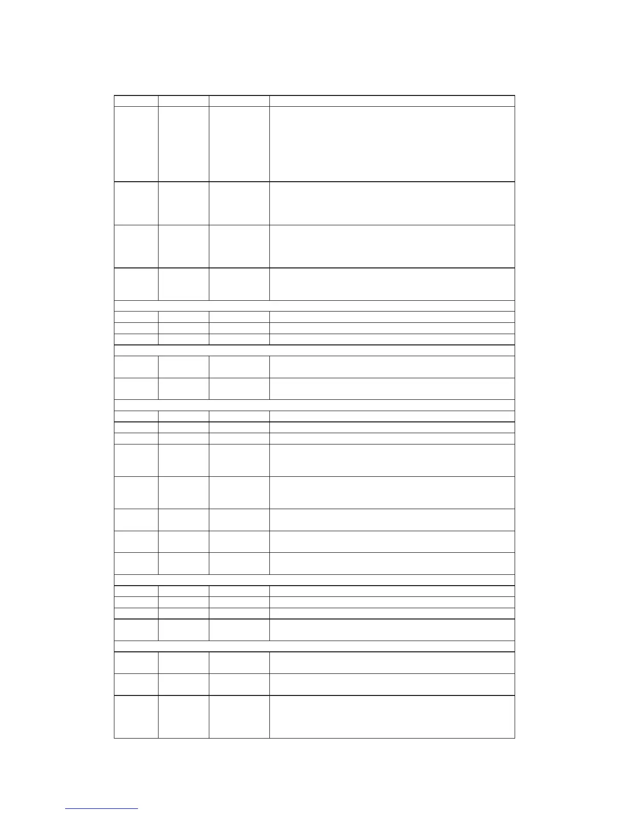
Pin Numbers Pin NAME Type Description
116 DIOW #
TTL Schmitt
Input 50K pull up
Device I/O write: Stop Ultra DMA burst
This is m ulti-function pin.
For Device I/O W rite, this signal is the strobe si gnal asserted by the host to
write device registers or the data port.
For Stop Ultra DMA, this signal shall be negated by host before data is
transferred in an Ultra DMA burst and is asserted by host during an Ultra
DMA burst to signal the termination of Ultra DMA burst.
117 DMARQ TTL Output
DMA request.
This signal is used for DMA data transfers between host and device and it
shall be asserted by the MT1368 when it is ready to transfer data to or from
the host. The direction of data transfer is controlled by DIO R# and DIO W#.
118-120,12
2-126,-128-
131,134-13
7
HD[15:0] TTL I/O
Host data bus.
This is an 8- or 16- bit bi-directional data interface between the host and
device; the lower 8 bits are used for 8-bit register transfers. Data transfers
are 16-bit wide.
138 HRST#
TTL Schmitt
Input 50K pull up
Host reset.
This signal is referred to as hardware reset and it is used by host to reset
the MT1368.
CLV/CAV Varipitch interface
140 VPVDD Power Power pin for varipitch VCO circuitry.
141 VCOCIN Analog Input Connect capacitor for compensator loop filter.
142 VPVSS Ground G round pin for varipitch VCO circuitry.
Miscellaneous
139 PRST#
TTL Schmitt
Input 50K pull up
Power-on reset, low active
143 TEST
TTL Input
50K Pull-Down
Test mode control pin, high active
Lag and Program mable I/O Interface
145 FLAGD TTL I/O Servo DSP flag.
146 FLAGC TTL I/O Servo DSP flag.
147 FLAGB TTL I/O Servo DSP flag.
148 FLAGA TTL I/O
Servo DSP flag. The internal flags of servo DSP can be selected to output
through FLAGA, FLAGB, FLAGC, and FLAGD pins. To program the
selection the m icro controller must write FLG MO D register.
150 IO3
TTL I/O
50K pull high
At non-flash m ode: programmable I/O or internal non-servo flags output.
At flash mode cycle: to monitor DSVSEL to device m aster or slaver. It is
recorded on DEVSEL
102hRW6
.
151 IO2
TTL I/O
50K pull high
At non-flash mode cycle: programmable I/O or internal non-servo flags output.
At flash m ode cycle: f lash RO M address FLA SH_ADR16.
152 IO1 TTL I/O
At non-flash mode cycle: programmable I/O or internal non-servo flags output.
At flash mode cycle: flash ROM output enable FLASH_OE#.
153 IO0
TTL I/O
50K pull high
At non-flash mode cycle: programmable I/O or internal non-servo flags output.
At flash mode cycle: flash ROM write enable FLASH_W R#.
SIO interface & Defect
154 SDATA TTL I/O RF serial data input/output.
155 SDEN TTL output RF serial data latch enable
156 SLCK TTL output RF serial clock output
157 BDO
TTL Input
50K pull down
Flag of defect data input status
Digital Power & Ground
57,75,104,1
44
DVDD3 Power +3.3V use for Internal digital circuitry and digital output pad
16,65,109,
133,100
DVDD Power +5V use for Internal digital circuitry and digital output pad
21,35,68,8
4,115,121,1
27,133,149
96
DVSS Ground Internal digital circuitry and digital output pad.
12
 Loading...