EasyManua.ls Logo

Santerno Sinus Penta - Programmable Functions; Controlled Stop in Case of Power Failure (Power Down); DC Braking; Motor Thermal Protection

Santerno Sinus Penta
47 pages
Print Icon
To Next Page IconTo Next Page
To Previous Page IconTo Previous Page
Loading...
ASSEMBLY INSTRUCTIONS
SINUS PENTA
MODULAR INVERTERS
28/47
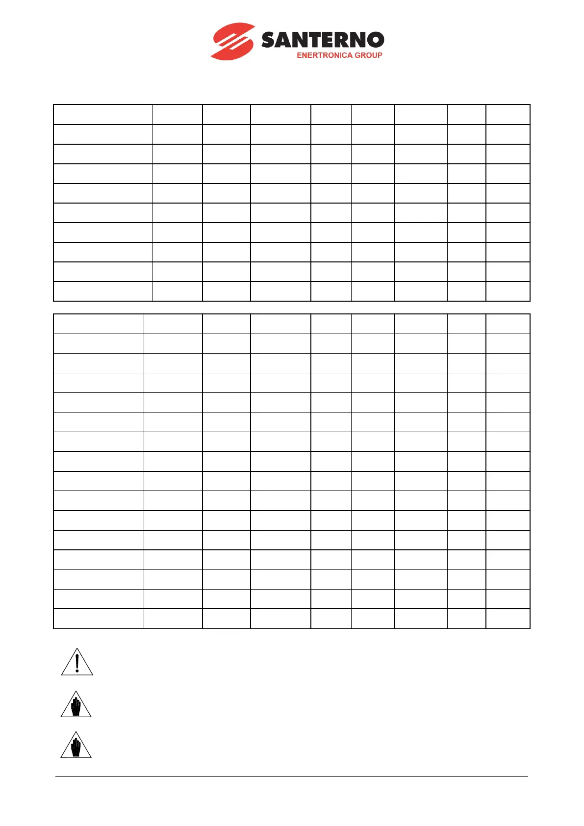
2.4.1.2. OPTICAL FIBRE CONNEC T IONS
Signal
Type of
connection
Cable
marking
From
Board
Connector
To
Board
Connector
IGBT command, phase U
double
optical fibre
G-U
Control unit
ES842
OP19-
OP20
Phase U1
ES887
CN9-
CN10
IGBT command, phase V
double
optical fibre
G-V
Control unit
ES842
OP13-
OP14
Phase V1
ES887
CN9-
CN10
IGBT command, phase W
double
optical fibre
G-W
Control unit
ES842
OP8-OP9
Phase W1
ES887
CN9-
CN10
IGBT command, phase U1
double
optical fibre
G-U1
Phase U1
ES887
CN1-CN4
Phase U1
ES841
OP4-OP5
IGBT command, phase V1
double
optical fibre
G-V1
Phase V1
ES887
CN1-CN4
Phase V1
ES841
OP4-OP5
IGBT command, phase
W1
double
optical fibre
G-W1
Phase W1
ES887
CN1-CN4
Phase W1
ES841
OP4-OP5
IGBT command, phase U2
double
optical fibre
G-U2
Phase U1
ES887
CN2-CN5
Phase U2
ES841
OP4-OP5
IGBT command, phase V2
double
optical fibre
G-V2
Phase V1
ES887
CN2-CN5
Phase V2
ES841
OP4-OP5
IGBT command, phase
W2
double
optical fibre
G-W2
Phase W1
ES887
CN2-CN5
Phase W2
ES841
OP4-OP5
Signal
Type of
connection
Cable
marking
From
Board
Connector
To
Board
Connector
IGBT fault, phase U
single optical
fibre
FA-U
Control unit
ES842
OP15
Phase U1
ES887
CN7
IGBT fault, phase V
single optical
fibre
FA-V
Control unit
ES842
OP10
Phase V1
ES887
CN7
IGBT fault, phase W
single optical
fibre
FA-W
Control unit
ES842
OP5
Phase W1
ES887
CN7
IGBT fault, phase U1
single optical
fibre
FA-U1
Phase U1
ES887
CN11
Phase U1
ES841
OP3
IGBT fault, phase V1
single optical
fibre
FA-V1
Phase V1
ES887
CN11
Phase V1
ES841
OP3
IGBT fault, phase W1
single optical
fibre
FA-W1
Phase W1
ES887
CN11
Phase W1
ES841
OP3
IGBT fault, phase U2
single optical
fibre
FA-U2
Phase U1
ES887
CN12
Phase U2
ES841
OP3
IGBT fault, phase V2
single optical
fibre
FA-V2
Phase V1
ES887
CN12
Phase V2
ES841
OP3
IGBT fault, phase W2
single optical
fibre
FA-W2
Phase W1
ES887
CN12
Phase W2
ES841
OP3
BU IGBT Fault[*]
single optical
fibre
FA-BU
Control unit
ES842
OP3
BU
ES841
OP8
Vbus reading
single optical
fibre
VB
Control unit
ES842
OP2
Phase W1
ES843
OP2
IGBT status, phase U
single optical
fibre
ST-U
Control unit
ES842
OP16
Phase U1
ES843
OP1
IGBT status, phase V
single optical
fibre
ST-V
Control unit
ES842
OP11
Phase V1
ES843
OP1
IGBT status, phase W
single optical
fibre
ST-W
Control unit
ES842
OP6
Phase W1
ES843
OP1
BU IGBT Command[*]
single optical
fibre
BO-BU
Control unit
ES842
OP4
BU
ES841
OP5
CAUTION
NEVER apply voltage to the equipment if optical fibre connectors are
disconnected.
NOTE
The braking units are optional.
NOTE
[*] The internal wiring for the dual configuration of the braking units is given in
section 2.5.

Other manuals for Santerno Sinus Penta

Related product manuals