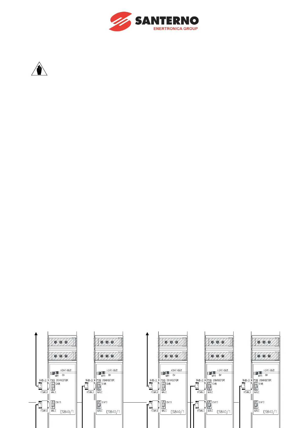
In the modular inverters wiring diagrams, the power supply units are defined as
illustrated in the diagram below:
Figure 1: Cascade connection of the power supply modules
Based on the inverter size, the Power Supply Unit 2 may be either the last unit in the chain (LAST in Size S75)
or the middle unit in the chain (MIDDLE in Sizes S80-S90).
Therefore, different settings are required for ES840/1 board, as described in section 2.6.1 later on in this
manual.


 To Next Page