Step 2: Prepare the Ceiling
Because of the wide variety of possible mounting situations, we can only provide general guidelines for installation. Study the following
information carefully, and adapt it as necessary to t your specic installation. The “General Guidelines” below and the information on
the following pages cover the most common mounting situations:
General Guidelines:
• Carefully determine the position of the mount, and its distance from the screen. This will require knowing the lens to screen distance
(see projector specications for set-up).
• Use the dimensions from the diagram below to drill hole locations in the ceiling.
The VMPR1 can be suspended from standard fasteners secured to a wood framing member.
3.71
3.71
5.25
Ø
5.25
Plate should
face the screen
in this direction
Note: Please read text on following page!
WARNING: Improper installation can cause serious personal injury! Make sure the structural members can support a redun-
dant weight factor ve times the total weight of the equipment you intend to support overhead. If the structure cannot support
a redundant weight factor ve times the total weight of the equipment, the structure must be reinforced before you install the
VMPR1.
Standard Fasteners Flush Mounting to a Wood Framing Member
The VMPR1 can be secured to a wood framing member through the two larger slots (5.25” apart) in the ceiling bracket using two 1/4”
lag screws for single stud mounting. If you have a solid back ceiling, and the area is accessible from above, you many also use four 1/4”
diameter machine screws, nuts, and washers. See Dimensional Drawing below.
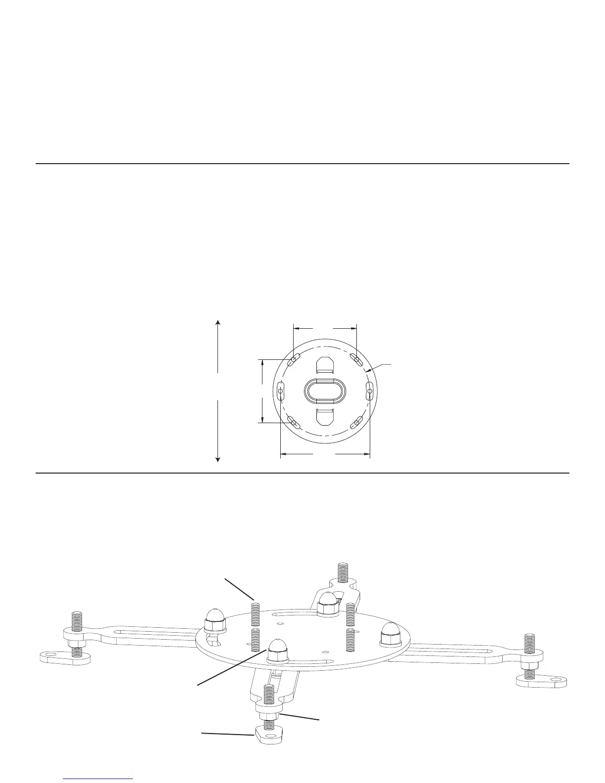
Dimensional Drawing
Step 3: Attach the bottom portion of the VMPR1 to the projector
Diagram 1
Note: Install the Universal Projector Interface (a) so one threaded stud is toward the front and one toward the back of the pro-
jector.
threaded studs
acorn hex nut
hex nut
adjustable foot
 Loading...