5/16 - 18 x .5
Button Head Cap Screw
Place Tabs of flush mount plate
over top of VMPR1 portion and add
5/16" screws
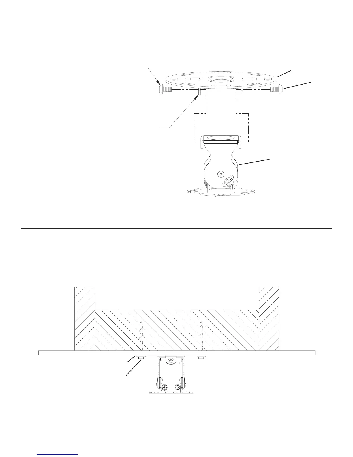
Step 4: Attach Ceiling Plate to Adjustment Bracket
Place Ceiling Plate (c) over top of the Adjustment Bracket (d), line up holes in plate with holes in Adjustment Bracket and secure using
the two 5/16-18 x 1/2” Button Head Cap Screws (l) provided. Tighten the Button Head Cap Screws with the Allen Key (s) See Diagram
4.
Diagram 4
c
l
d
Step 5: Ceiling Installation Procedures
Proceed to mount the top assembly to the ceiling using one of the appropriate hardware combinations mentioned in Step 2. Diagram
below shown attaching a Lag Bolt (t) with a Lag Bolt Washer (r) to a single wood stud or joist. See Diagram 5 for assistance.
Note: Reference Step 2 to install Ceiling Plate (c). Note the dimensional drawing in Step 2.
Diagram 5
r
t
 Loading...