*1 Not including the resistance of fuse.
*2 The maximum value when the pointer was moved by
charged current in the capacitor.
DCVCV
DCACV
0.1
±5 % against
full scale
±5 % against
full scale
±4 % against
full scale
±3 % against
full scale
±3 % against
full scale
±3 % against
full scale
±3 % of arc
±5 % of arc
Approximate Value
Approximate Value
Approximate Value
Input impedance 20 kΩ/V
Input impedance 40 k
Ω/V
Input impedance 9 kΩ/V
Current across test pins
Input impedance 9 k
Ω/V
30 Hz ~ 100 kHz within
±3 % f.s. (AC 10 V range)
Center value 20 Ω
Max. value 2 kΩ
Release voltage 3 V
*1 Voltage drop 0.1 V
*1 Voltage drop 0.25 V
*2
Input impedance 9 kΩ/V
250/1000
10/50/250/750
50
µ
2.5 m/25 m/0.25
2 k/20 k/200 k/2 M
(X1/X10/X100/X1 K)
-10 dB
~ +
22 dB
(for 10 VAC)
~ +
62 dB
0 ~ 150 mA at X1 range
0 ~ 15 mA at X10 range
0 ~ 1.5 mA at X100 range
0 ~ 150 µA at X1 K range
0 ~
1.5 µA at X100 K range
200 M
(X100 K)
10
µ
F
DC 25 kV
1000 atX10 range
HV-10T probe
HFE-6T probe
±
5/
±
25
DCV
(NULL)
ACV ~
C
dB
LI
HV (DC
high volt)
h
FE
Use the optional probe
Ω
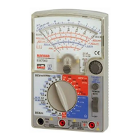
YX360TRF
MULTITESTER
INSTRUCTION MANUAL
05-130620402040
SANWA ELECTRIC
INSTRUMENT CO.,LTD.
Dempa Bldg., 4-4 Sotokanda 2-Chome
Chiyoda-Ku,Tokyo,Japan
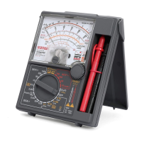
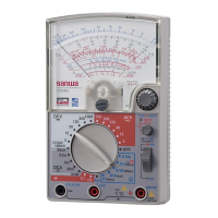
NAMES OF COMPONENTS
Test probe (black)
Test pins
Finger guards
Test probe (red)
Removable
test pin covers
When not
covered
− 1 − − 2− − 3−
INTRODUCTION
Thank you for purchasing a SANWA tester Model YX360TRF. You are
kindly requested to thoroughly read this manual before use for safety.
Especially, “SAFETY INFORMATION” and “MEASURING PROCE-
DURE” are important. Keep this manual together with the tester so as
no to lose it.
Fig. 1
SAFETY INFORMATION
SPECIFICATIONS
The following are precautions to prevent accidents such as electrical
shocks.
Be sure to read them before using the tester.
Symbols
The following cautionary signs appear on the multitester and
in this manual.
Disobedience to instructions with this sign may lead to trouble
with the tester and accidents such as electrical shock.
This sign cautions that high voltage is applied to parts marked
with it.
Precautions for Safety Measurement
To ensure that the meter is used safely, follow all safety and operat-
ing instructions.
11. Never use the meter on the electric circuits that exceeds 3 kVA.
12. Pay special attention when measuring the voltage of AC 33 Vrms
(46.7 V peak) or DC 70 V or more to avoid injury.
13. Never apply input signals exceeding the maximum rating input
value.
14. Never use the meter for measuring the line connected with equip-
ment (i.e. motors) that generates induced or surge voltage since it
may exceed the maximum allowable voltage.
15. Never use the meter if the meter or test leads are damaged or broken.
16. Never use an uncased meter.
17. Be sure to use a fuse of the specified rating or type. Never use a
substitute of the fuse or make a short circuit of the fuse.
18. Always keep your fingers behind the finger guards on the probe
when making measurements.
19. Be sure to disconnect the test pins from the circuit when changing
the function or range.
10. Before starting measurement, make sure that the function and
range are properly set in accordance with the measurement.
11. Never use the meter with wet hands or in a damp environment.
12. Never use test leads other than the specified type.
13. Never open the case except when replacing batteries or fuses. Do
not attempt any alteration of original specifications.
14. To ensure safety and maintain accuracy, calibrate and check the
meter at least once a year.
15. Indoor use only.
WARNING
− 5− − 6− − 7−
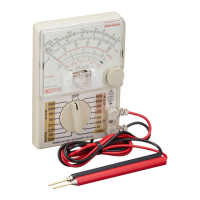
BODY COVER, TEST LEADS, HAND STRAP
Use of Cover (example for the body cover)
When this tester is out of use:
Attach the cover to the panel face for safekeeping.
When measuring:
Attach it either to the rear case side
or use it as a stand as shown below.
Storage of Test Leads
When placing the test leads in the
storage space, roll it 3 times, then
put in the test pin side first as shown
below.
Attachment of Hand Strap
1 Loosen the screws fixing the rear
case and remove it.
2 Hand strap is attached to con-
necting point.
3 Put back the rear case where it
was and fix it with the screws.
Fig. 2
− 4−
SCALE READING
Range Multiplied
Ω X 100 k X 100 k
Ω X 1 k X 1 k
Ω X 100 X 100
Ω X 10 X 10
Ω X 1 X 1
DCV 250 X 1
DCV 2.5 X 0.01
DCV 0.25 X 0.001
ACV 250 X 1
DCA 0.25 X 0.001
DCA 25 m X 0.1
DCA 2.5 m X 0.01
DCV 50 X 1
ACV 50 X 1
DCA 50 µ X 1
DCV 0.1 X 0.01
Range Multiplied
DCV 10 X 1
DCV 1000 X 100
ACV 750 X 100
ACV 10 X 1
C (µF) X 1
DCV ± 25 X 1
DCV ± 5 X 1
150 mA at X 1 X 10
15 mA at X 10 X 1
1.5 mA at X 100 X 0.1
150 µA at X 1 k X 10
1.5 µA at X 100 k X 0.1
LV X 1
h
FE
X 1
ACV 10 X 1
ACV 50 14 dB added
ACV 250 28 dB added
ACV 750 40 dB added
General Specifications
(Temperature : 23±2 ˚C humidity 75 % RH max. No condensation)
Drop shock proof
A taut-band structure is adopted in the meter part.
The meter part is designed to withstand shock.
Circuit protection
The circuit is protected by fuse even when voltage of up
to AC 230 V is impressed on each range for 5 seconds.
Internal battery
Internal fuse
R6 (IEC) or UM-3 1.5 V X 2
F500 mAH/250 V Ø5.2 X 20 mm Fast acting fuse
Operating temperature
and humidity range
5 ~ 31 ˚C, 80 %RH max.
31< ~ 40 ˚C, 80 ~ 50 %RH (decreasing linearly)
Withstand voltage
Dimensions and mass
6 kV AC (1 min.) between input terminal and case
159.5 X 129 X 41.5 mm/ approx. 320
g
Storage temperature/
Humidity
-10 ~ 50 ˚C 70 %RH max. No condensation
noitacificepSsmetI
Application
This instrument is portable multitester designated for meas-
urement of weak current circuits.
The specifications described in this manual are subject to
change without notice.
Measurement Range and Accuracy
Function Full scale value Accuracy Remarks
0.25/2.5/10/50
±3 % against
full scale
DRAWING No.YX360TRF 05-1306 2040 2040
APPLICATION
•
HV probe, HV-10T
•
h
FE
probe, HFE-6T
•
Test lead for repair, TL-6ITb
Accessories Instruction manual 1, Hand strap 1,
Environmental condition
Operating a ltiude up to 2000 m pollution degree 2
YX360TRF04B4初11.5.129:31AMページ1
0
Ω
・