EasyManua.ls Logo

Sanwa CP-7D User Manual

Sanwa CP-7D
2 pages
To Next Page IconTo Next Page
Page #1 background imageLoading...
Page #1 background image
DRAWING No.CP-7D 17-1805 2040 2040
CP-7D
マルチテスタ
MULTITESTER
取扱説明書
INSTRUCTION MANUAL
17-1805 2040 2040
社=
東京都千代田区外神田
2
4
4電波ビル
郵便番号=101
-
0021話=東(033253
4871
(代)
大阪営業所= 阪市浪速区恵美須西 2
7
2
郵便番=556
-
0003話=大(066631
7361
(代)
植物油インキを使用しています。
1 − 1 −
3 − 3 −
DC 600 V / AC 600 V
または、Peak 840 V
DC 50 V / AC 50 V
または、Peak 70 V
DC 1.5 V / AC 1.5 V
または、Peak 2 V
DC 5 V / AC 5 V
または、Peak 7 V
7 − 7 −
6 Vを測定する場合は12 Vレンジ、15 Vを測定する場
合は30 Vレンジのように測定する値よりも大きく、か
つ近いレンジを選びます。測定値の見当がつかない場
合は、最大レンジ(500 V)で測定してみます。
5 − 5 −
DC 10 V
AC 250 V
9 − 9 −
0.25/2.5/10/50/250/500 Vまでの6レンジ
DC 500 V
− 12 −
0.25 m/25 m/500 mAまでの3レンジ
2 − 2 −
6 kVAを超える電力ラインでは使用しないこと。
AC 33 Vrms(46.7 Vpeak)またはDC 70 V以上の電
圧は人体に危険なため注意すること。
− 4 −
番号 使用レンジ 読み取り倍率
Ω  ×1
Ω ×1 ×1
Ω ×10 ×10
DCV 0.25 ×0.001
DCV 2.5 ×0.01
DCV 250 ×1
ACV 250 ×1
DCmA 0.25
×0.001
DCmA 25
×0.1
− 8 −
0 〜200 Ω程度の測定に
:20 Ω〜2 kΩ程度の測定に
:1 kΩ〜1 MΩ程度の測定に
11 − 11 −
36 dB
DC 500 mA
−20〜36 dB
のdB目盛はACV 10 Vのして、0 dB=
0.775 Vとして目盛られています。従ってインピーダン
ス600 Ωの回路の場合のみ 0 dB=1 mWとしてのdB値を
求めることができます。
− 6 −
0 Ω調整器つまみ
− 10 −
AC 500 V
10/50/250/500 Vまでの4レンジ
10 Vレンジでは30 Hz〜100 kHzの範囲で使用してくだ
さい。(±3 %フルスケール)
50 Vレンジでは30 Hz〜20 kHzの範囲で使用してください。
(±3 %フルスケール)
13 − 13 −
赤、黒のテストピンをショートして0 Ω調整つまみを
回し、指針をΩ目盛の0位置に合わせます。
Question and Answer IconNeed help?

Do you have a question about the Sanwa CP-7D and is the answer not in the manual?

Sanwa CP-7D Specifications

General IconGeneral
BrandSanwa
ModelCP-7D
CategoryTest Equipment
LanguageEnglish

Summary

Safety Information

Warning Mark and Symbol Explanation

Explains symbols used in the manual and on the device, indicating safety precautions.

Warning Statements for Safe Use

Lists crucial safety warnings to prevent personal injury like burns or electric shock.

Maximum Overload Protection Input Values

Details the maximum allowable input values for each range to prevent damage.

Application and Feature

Application

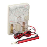
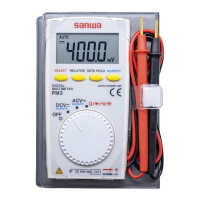
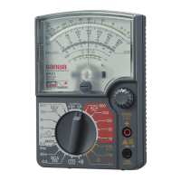
Describes the intended use of the analog multimeter for small circuits and devices.

Features

Highlights key characteristics such as compact size, circuit protection, and lead retention.

Names of Each Part

How to Measure

How to Read Indication

Explains how to correctly read the measurement value from the meter's scale.

How to Set Range

Guidance on selecting the appropriate range and function for measurement.

Preparation Before Measurement

Steps for zero adjustment before resistance measurement and optimal range selection.

Measuring Voltage (V)

Detailed procedures for measuring DC and AC voltages safely and accurately.

Measuring DC Current (DCmA)

Procedure for measuring DC current, including correct connection in series.

Measuring Resistance (Ω)

Method for measuring resistance values and checking circuit continuity.

Function Description

Pre-Operation Check

Specifications

Troubleshooting

Memo

Related product manuals