Do you have a question about the Sanyo C1211 and is the answer not in the manual?
Guidance on when and how to seek assistance for installation or special problems.
Statement regarding the manufacturer's responsibility for improper installation.
Safety precautions for electrical wiring installation and connection.
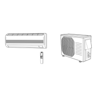
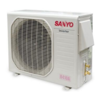
Guidelines for safely moving the indoor and outdoor air conditioner units.
Key considerations and procedures for installing the air conditioner in various locations.
Steps and methods for properly connecting refrigerant lines for optimal performance.
Safety measures and practices to follow during maintenance and repair of the unit.
Comprehensive technical data for the RS1211 and C1211/CL1211 air conditioning units.
Detailed specifications for key internal and external components of the units.
Technical details for auxiliary components such as transformers and thermistors.
Graphical data illustrating operating current based on ambient and indoor temperatures.
Chart showing low pressure performance against varying temperature conditions.
Explanation of the system's operation for maintaining desired room temperatures.
Description of the automatic function to prevent indoor coil freezing.
Details on how the indoor fan speed automatically adjusts based on room conditions.
Information on how the outdoor fan speed is regulated according to ambient temperature.
A visual overview of the electrical system's components and connections.
Detailed wiring layout for the Printed Circuit Board (PCB) assembly.
Essential preliminary checks of wiring, power, and connections before diagnosing issues.
Steps to diagnose why the air conditioner fails to operate entirely.
Information on the conditions and settings for general cooling operation.
Steps to diagnose why only the outdoor unit fails to run.
Troubleshooting specific component failures like indoor/outdoor fans or compressors.
Addressing issues such as poor cooling or excessive cooling during operation.
Diagnosing problems related to a defective indoor heat exchanger coil temperature sensor (TH1).
Procedure for measuring insulation resistance of various electrical parts and wiring.
Method to verify fuse continuity on the PCB using a multimeter.
Steps for testing the condition and functionality of motor capacitors.
Visual guide to identifying relays, switches, and other electrical parts.
| Power Supply | 220-240V, 50Hz |
|---|---|
| Refrigerant | R22 |
| Weight (Indoor Unit) | 9 kg |
| Cooling Capacity | 3.4 kW |
| Operating Temperature (Cooling) | 18°C to 43°C |