Do you have a question about the Sanyo C1822 and is the answer not in the manual?
Critical safety measures for electrical wiring, requiring qualified personnel.
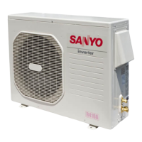
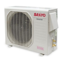
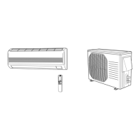
Advice on suitable locations and support for unit installation.
Best practices for connecting refrigerant lines to ensure leak-free operation.
Essential safety practices for technicians during unit maintenance and repair.
Detailed specifications for the air conditioning unit models.
Specifications for key indoor and outdoor unit components.
Specifications for auxiliary components like transformers and thermistors.
Charts showing operating current vs. ambient and indoor temperatures.
Charts detailing low pressure characteristics under various conditions.
Explanation of how room temperature is controlled via compressor cycling.
Description of the system's freeze prevention mechanism.
How the indoor fan speed automatically adjusts based on room temperature.
Control logic for the outdoor fan speed in C1822 model.
Control logic for the outdoor fan speed in CL1822 model.
Visual representation of the unit's electrical connections and components.
Detailed wiring diagram for the Printed Circuit Board assembly.
Initial checks and preparations before commencing troubleshooting.
Troubleshooting steps when the unit fails to operate.
Diagnosing issues with individual components like fans or compressor.
Troubleshooting common operational problems and abnormalities.
Diagnosing and addressing issues with the indoor coil temperature sensor.
Procedure for measuring the insulation resistance of unit components.
Method for checking fuse continuity on the PCB assembly.
Procedure for testing the functionality of motor capacitors.
Visual identification and characteristics of various electrical components.
| Cooling Capacity | 18000 BTU/h |
|---|---|
| Power Supply | 220-240V, 50Hz |
| Power Consumption | 1.8 kW |
| Refrigerant | R22 |
| Type | Split System |
| Operating Temperature | 18°C to 43°C |