DESCRIPTION
L
—
L
PIN 1/0
PORT NAME
TERMINAL NAME
DESCRIPTION
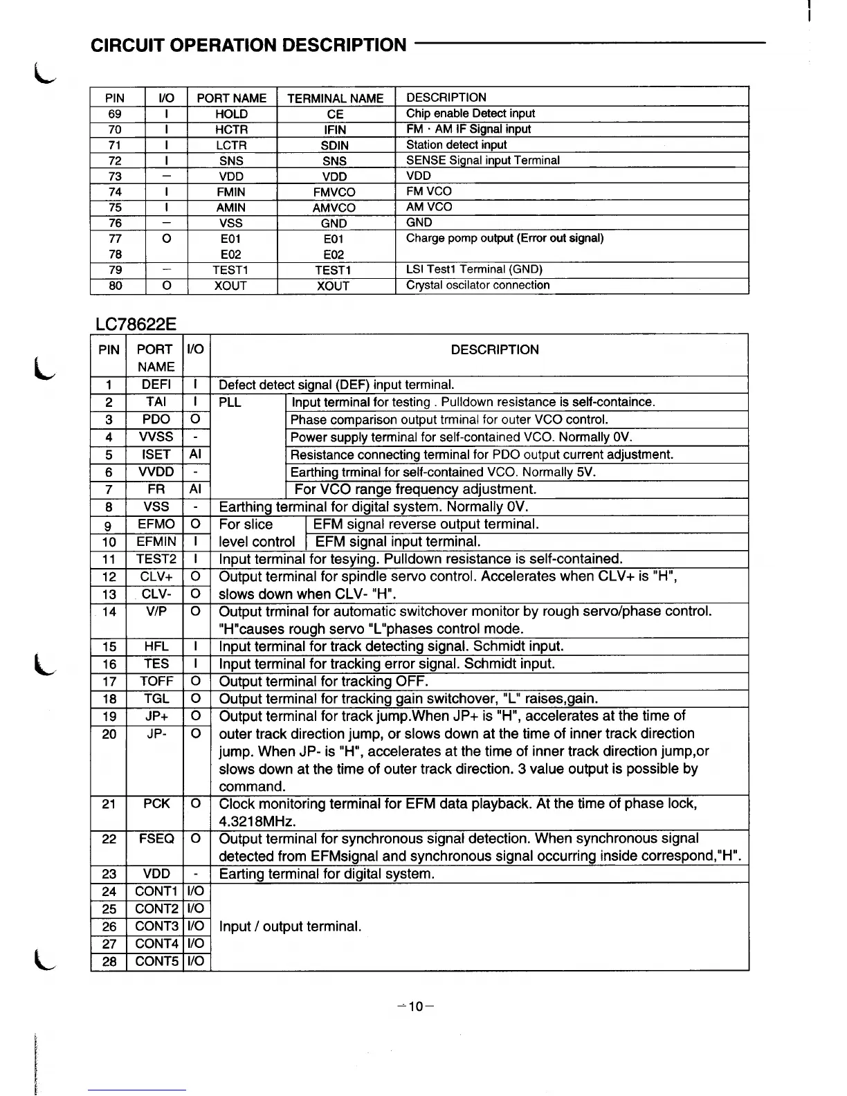
69
I
HOLD
CE
Chip enable Detect input
70 I
HCTR
IFIN
FM . AM IF Signal input
71 I
LCTR
SDIN
Station detect input
72 I
SNS
SNS
SENSE Signal input Terminal
73 –
VDD
VDD
VDD
74
I
FMIN
FMVCO
FM VCO
75 I
AMIN
AMVCO
AM VCO
76 –
Vss
GND
GND
77 0
EO1
EO1
Charge pomp output (Error out signal)
78
E02
E02
79 –
TEST1
TEST1
LSI Testl Terminal (GND)
80 0
XOUT XOUT
Crvstal oscilator connection
LC78622E
PIN PORT 1/0
DESCRIPTION
NAME
1 1 ,
1
DEFI I I
I Defect detect sianal (DEF) inrmt terminal.
2
TAI
3
PDO
4
Wss
5
ISET
6
WDD
7
FR
8
Vss
9
EFMO
10
EFMIN
11
TEST2
12
CLV+
13
CLV-
14
VIP
+=
15
HFL
16
TES
17
TOFF
18
TGL
19
JP+
-.7 .
I
PLL
Input terminal for testing . Pulldown resistance is self-containce.
o
Phase comparison output trminal for outer VCO control.
Power supply terminal for self-contained VCO. Normally OV.
Al
Resistance connecting terminal for PDO output current adjustment.
Earthing trminal for self-contained VCO. Normally 5V.
Al
For VCO range frequency adjustment.
Earthing terminal for digital system. Normally OV.
o
For slice
EFM signal reverse output terminal.
I
level control EFM signal input terminal.
I
Input terminal for tesying. Pulidown resistance is self-contained.
o
Output terminal for spindle servo control. Accelerates when CLV+ is “H”,
o
slows down when CLV- “H”.
o
Output trminal for automatic switchover monitor by rough servolphase control.
“H’’causes rough servo “L’’phases control mode.
I
Input terminal for track detecting signal. Schmidt input.
I
lnDut terminal for tracking error signal. Schmidt input.
o
Output terminal for track~g OFF. -
0
Output terminal for tracking gain switchover, “L” raises, gain.
o
Output terminal for track jump.When JP+ is “H”, accelerates at the time of
20
JP-
Io
outer track direction jump, or”slows down at the time of inner track direction
jump. When JP- is “H”, accelerates at the time of inner track direction jump,or
slows down at the time of outer track direction. 3 value output is possible by
command.
21
PCK o
Clock monitoring terminal for EFM data playback. At the time of phase lock,
4.321 8MHz.
22
FSEQ o
Output terminal for synchronous signal detection. When synchronous signal
detected from EFMsignal and synchronous signal occurring inside correspond,’’H”.
23
VDD
-
Earting terminal for digital system.
24 CONT1
1/0
+=
25 CONT2
26 CONT3
27 CONT4
4
1/0 Input / output terminal.
1/0
28 I CONT5 11/0
=lo–
 Loading...
