L
WIRING
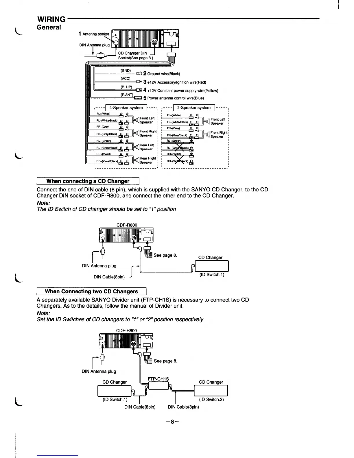
General
1 Antennaso
DIN
Antyma
+J
CD ChangerDIN ~
I
Socket(Seapege8.)
fi( ,,
111111II
(GND)
@ 2 Groundwire(Black)
111111II
.,
(ACC)
~ 3
+12VAccesso@gnitionwire(Rad)
111111~
(B. UP)
=4 +12V Constant Dower suodv wire(Yellow)
1111/
,,, . ,
(P.ANT)
D 5 power antenna control wire(Blue)
&
---- 4-Spaaker system ---.,
I FL+(WWie)
ee
3
Front Letl ~
I FL-(whir*@ e e
Speaker :
I!Ei
‘ FR+(Grny)
@e
,
‘ FR-(Gray~lesk)
3
Front Right f
e
Speaker I
a
RL+ Green
@
,
a
Rear Left ~
1 RL<GrewShck)
Speaker [
/
----
2-Spaaker system ,
-----
,
FL+(wm)
,
,
t
@e
!-
“..-... ,,.. I
rrorn tog
FR-(Gm@.Iwk) e &_ljQ Spgaker
I
,
RL-(Gr&Q Iack) e
o
‘--------------------------
J
‘___________________________ .’
When connecting a CD Changer
Connect the end of DIN cable (8 pin), which is supplied with the SANYO CD Changer, to the CD
Changer DIN socket of CDF-R800, and connect the other end to the CD Changer.
Note:
The ID Switch of CD changer should be set to ‘7” position
CDF-R800
DIN
When Connecting two CD Changers
A separately available SANYO Divider unit (FTP-CH1 S) is necessary to connect two CD
Changers. As to the details, follow the manual of Divider unit.
Note:
Set the ID Switches of CD changers to”1” or “2” position respectively.
CDF-R800
l-’
~@
See page 8.
DIN
Antenna plug
II
DIN Cable(8pin) DIN”Cable(8pin)
–8–
 Loading...
