EasyManua.ls Logo

Sanyo CM21KX81 User Manual

Sanyo CM21KX81
30 pages
To Next Page IconTo Next Page
Page #1 background imageLoading...
Page #1 background image
V
I
D
E
O
L
-
A
U
D
I
O
-
R
T
V
/
A
V
M
E
N
U
P
SERVICE MANUAL Colour Television
Product Code: 111358217 (CM21KX81)
111358247 (CM21KX81A)
111368013 (CM21LX81)
111368033 (CM21LX81A)
111368713 (CM21MX81)
111368733 (CM21MX81A)
Original Version
Chassis Series: AC5-G1
C4VW/C4VWA/C5RR/C5RRA/C6YR/C6YRA
FILE NO.
(Middle East)
Give complete “SERVICE REF. NO. for
parts order or servicing. It is shown on the
rating plate at the cabinet back of the unit.
This T.V. receiver will not work properly in
foreign countries where the television trans-
mission system and power source differ
from the design specifications. Refer to the
specification table.
Specifications
Power Source . . . . . . . . . AC110-240V, 50Hz/60Hz.
Colour System . . . . . . . . PAL/SECAM/NTSC4.43/NTSC/PAL-60Hz
Television System . . . . . . B/G, D/K, K’, I, M/M
Channel Coverage . . . . . VHF: E2-E12, R1-R12, K1-K9, A2-A13, J1-J12
UHF: 21-69, A14-A69, J13-J62
CATV: S1-S41, X, Y, Z, Z+1, Z+2
Video IF . . . . . . . . . . . . . . 38.0MHz
Aerial Input Impedance . . 75
Ext. Terminals
Video inputs: Phono jack 2 (1Vp - p, 75Ω)
Audio inputs: Phono jack (L/R) 2(436mVrms, more than 40KΩ)
Video monitor outputs: Phono jack 1(1Vp - p, 75Ω)
Audio monitor outputs: Phono jack (L/R) 1(436mVrms, less than 600Ω)
Sound Output (RMS) . . . . 5W + 5W
Speaker . . . . . . . . . . . . . 6 cm 12 cm 2 pcs.
Dimensions . . . . . Model CM21KX81/A: 625 (W) 460.5 (H) 384 (D)mm
Model CM21LX81/A: 645 (W) 465 (H) 484 (D)mm
Model CM21MX81/A: 645 (W) 465 (H) 484 (D)mm
Weight . . . . . . . . Model CM21KX81/A: approx. 21.2 Kg
Model CM21LX81/A, CM21MX81/A: approx. 20.8 Kg
Specifications subject to change without notice.
REFERENCE NO. SM5110573
V
I
D
E
O
L
-
A
U
D
I
O
-
R
T
V
/
A
V
M
E
N
U
C
H
V
I
D
E
O
L
-
A
U
D
I
O
-
R
T
V
/
A
V
M
E
N
U
C
H
0
7
14
85
23
6
9
P
P
JXMYA
-/--
PP
TV/AV
A B
CH SCAN
TIMER
MENU
PIC MODE
SWAP
BASS
SURROUND
Service Ref. No. CM21KX81-00
CM21KX81A-00
CM21LX81-00
CM21LX81A-00
CM21MX81-00
CM21MX81A-00
Model No. CM21KX81
CM21KX81A
CM21LX81
CM21LX81A
CM21MX81
CM21MX81A
Question and Answer IconNeed help?

Do you have a question about the Sanyo CM21KX81 and is the answer not in the manual?

Sanyo CM21KX81 Specifications

General IconGeneral
Screen Size21 inches
Display TechnologyCRT
Aspect Ratio4:3
ModelCM21KX81
BrandSanyo
InputsComposite

Summary

TV Specifications

Safety Notice

Safety Precautions

General safety rules for servicing and handling the TV receiver.

X-Radiation Precaution

Precautions regarding X-radiation emissions from the picture tube during servicing.

Product Safety Notice

Importance of using specified replacement parts for product safety.

Chassis Block Diagrams

Main Signal Processing Circuit

Illustrates the main signal flow and component interconnections within the TV.

Chassis Block Diagrams

System Control

Details the control system block diagram and its interface with other components.

IC Block Diagrams

IC201: IF, Video, Chroma, Deflection

Detailed block diagram for the LA76818 IC, covering IF, video, chroma, and deflection processing.

IC Block Diagrams

IC201: IF System Block Diagram

Illustrates the IF system block diagram of the LA76818 IC for signal reception and processing.

IC Block Diagrams

IC501: Vertical Output / IC3701: Audio Control

Block diagrams for vertical output (LA78040/TDA9302H) and audio control (NJW1142MP) ICs.

Service Information

Protection Circuit

Explains the TV's built-in power supply protection circuit and its function during malfunctions.

Releasing Protective Circuit

Instructions on how to release the protective circuit and restore power supply.

Service Adjustments with Memory IC Replacement

Initializing Procedure

Steps to initialize the memory IC after replacement for optimal performance.

Required Service Adjustments

Lists adjustments needed after memory IC replacement, referencing service mode items.

Service Adjustments with Memory IC Replacement

Entering Service Mode

Guide on how to access the service mode using the remote control for adjustments.

Service Mode Adjustments

Item 01: RF AGC Adjustment

Procedure for adjusting RF AGC for optimal signal reception and minimizing snow noise.

Item 02: Horizontal Centre (H-PHA)

Steps to adjust the horizontal centering of the picture using the H-PHA service item.

Item 04: Vertical Size (V-SIZ)

Procedure for adjusting the vertical size of the picture display.

Item 05: Vertical S-Correction (V-SCO)

How to adjust the vertical S-correction for accurate picture geometry.

Item 06: Vertical Linearity (V-LIN)

Method to adjust vertical linearity for proper vertical picture proportion.

Service Mode Adjustments

Items 14-17, 19-21: Grey Scale

Detailed steps for adjusting grey scale and white balance for accurate color reproduction.

Service Adjustments

B-Voltage Supply Checking

Procedure to check and adjust the B-voltage supply using a DC meter and VR631.

High Voltage Checking

Steps to check the high voltage output and its limits for safe operation.

Focus Adjustment

Instructions to adjust the focus control on the FBT for a sharp picture.

Special Functions

Volume Lock Setting

How to set a maximum sound volume limit.

Tuning Lock Setting

How to enable tuning lock to prevent channel changes.

Music Mode Setting

Setting the TV to Music Mode for audio-only playback.

AV Start Setting

Configuring the TV to start in AV mode automatically.

Purity and Convergence Adjustment

Purity Adjustment

Steps for adjusting color purity and raster centering after component replacement.

Centre Convergence Adjustment

Procedure for adjusting the convergence of Red, Green, and Blue guns in the center of the screen.

Outer Area Convergence Adjustment

Method to adjust convergence for the outer areas of the picture screen.
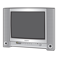
Cabinet Parts List

Chassis Electrical Parts List

Related product manuals