P. P
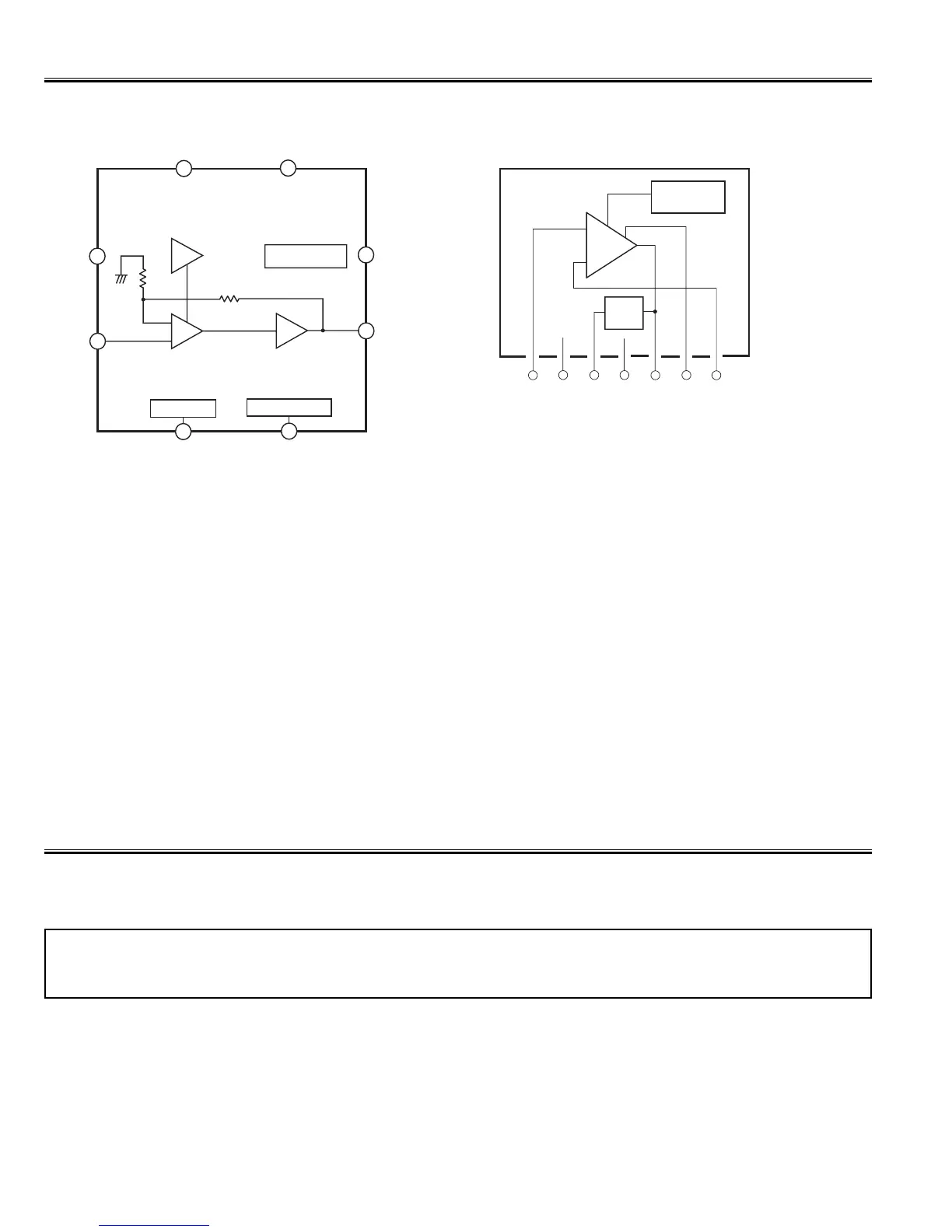
When an abnormality occurs during TV reception, it causes pin 23 of the Processor to go continually Low (less
than 2.0V) for about 2 second. The Processor detects that this has occurred and outputs the signal from pin 36 to
switch off the power supply lines.
Releasing the protective circuit and restoring power supply
To release the protective circuit and restore power supply, turn the power to the TV set OFF and then ON again via
either the main power switch or the ON-OFF button on the remote control. This will work only if the power supply
trouble was temporary. If there is permanent trouble such as a damaged circuit, power cannot be restored and the
circuit will have to be repaired.
This TV set has a built-in power supply protection circuit.
It is provided to protect the TV set in case of a power supply circuit malfunctions. When something abnormality occurs
during TV reception, the TV set goes to the stand-by mode.
Protection Circuit

 Loading...